
Case built-in heat dissipation device based on loop heat pipe

A loop heat pipe and heat dissipation device technology, which can be used in chassis/cabinet/drawer parts, cooling/ventilation/heating modification, modification with liquid cooling, etc. It can improve the use range and practicability, improve the efficiency of heat dissipation, and improve the use environment.

Active Publication Date: 2021-03-26
泰睿(北京)技术服务有限公司
View PDF11 Cites 1 Cited by
  • Summary
  • Abstract
  • Description
  • Claims
  • Application Information

AI Technical Summary

Problems solved by technology

[0006] The object of the present invention is to provide a built-in cooling device based on a loop heat pipe, to solve the problem that the length of the installation structure of the existing built-in cooling device based on a loop heat pipe in the market is fixed. , when the cooling device is cooling different types of electrical components inside the chassis, it is inconvenient to install with the main body of the chassis, and the existing built-in cooling device based on the loop heat pipe cannot dissipate the heat well Conducted out, so that the emitted heat is around the condenser tube, which affects the cooling efficiency of the later stage

Method used


Image

  • Case built-in heat dissipation device based on loop heat pipe
  • Case built-in heat dissipation device based on loop heat pipe
  • Case built-in heat dissipation device based on loop heat pipe

Examples


Embodiment Construction

[0026] Next, the technical solutions in the embodiments of the present invention will be apparent from the embodiment of the present invention, and it is clearly described, and it is understood that the described embodiments are merely embodiments of the present invention, not all of the embodiments. Based on the embodiments of the present invention, there are all other embodiments obtained without making creative labor without making creative labor premises.

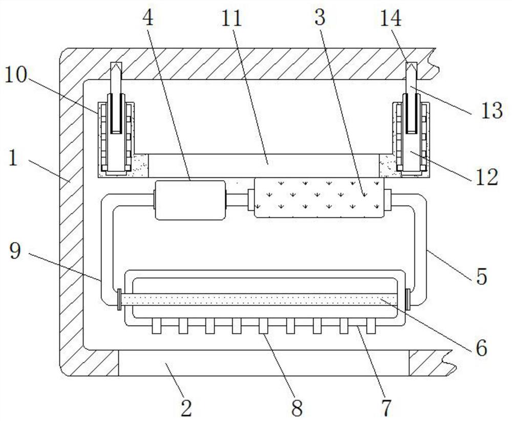
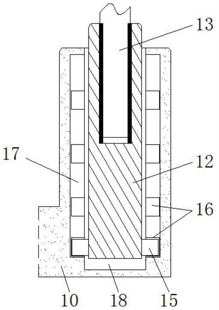
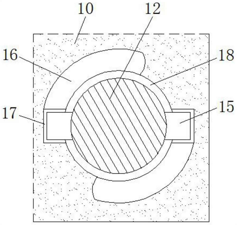
[0027] See Figure 1-6 The present invention provides a technical solution: a loop-based cabinet heat dissipation device including a chassis housing 1, a heat dissipation port 2, an evaporator 3, a reservoir 4, a steam tube 5, a condenser 6, cooling Box 7, the heat dissipating fin 8, the liquid traction pipe 9, the mounting plate 10, the channel 11, the vertical rod 12, the threaded rod 13, the mounting groove 14, the bump 15, the first adjustment slot 16, the second adjustment slot 17, The accommodating groove 18, the insi...


PUM


Abstract

The invention discloses a case built-in heat dissipation device based on a loop heat pipe. The case built-in heat dissipation device comprises a case shell, a heat dissipation opening, an evaporator and a liquid storage device. The heat dissipation opening is formed in the front side surface of the case shell, the evaporator is placed in the case shell, the left end of the evaporator is connectedwith the liquid storage device through a pipeline, the right end of the evaporator is connected with a steam pipe through a flange plate, the bottom end of the steam pipe is connected with a condensation pipe through the flange plate, a cooling frame is fixed to the outer side of the condensation pipe, and the left end of the condensation pipe penetrates through the cooling frame and is connectedwith a liquid co-flow pipe through a two-way pipeline. The top end of the liquid co-flow pipe is connected with the left end of the liquid storage device through the flange plate, and a mounting plateis fixed to the rear side surface of the evaporator. The case built-in heat dissipation device based on the loop heat pipe is provided with a vertical rod and the mounting plate, and the vertical rodcan slide in an accommodating groove in the mounting plate so that the vertical rod can well move.

Description

Technical field [0001] The present invention relates to the technical field of chassis built-in heat sink, and is specifically a loop-based electronic heat dissipation device based on a loop heat pipe. Background technique [0002] The chassis built-in heat sink refers to the collective of the device that is heat-dissipated in the chassis and the electrical components in the chassis, and some electrical components will be installed in the chassis. These electrical components themselves generate a certain amount of heat, heat High words affect these electrical components, the built-in heat sink is installed in the chassis of the computer host or in some equipment chassis for heat dissipation to ensure that the temperature in the chassis is normal, avoiding the temperature over the chassis and affecting the chassis. The use of electrical components in the market, currently in the market, the types of built-in heat dissipation devices in the market are varied, and there is currently...

Claims


Application Information

Patent Timeline
IPC IPC(8): H05K7/20H05K5/02
CPCH05K7/20409H05K7/20309H05K7/20318H05K5/0213
Inventor 张明放
Owner 泰睿(北京)技术服务有限公司
Learn More