
Meat can trademark printing device

A technology for printing devices and cans, which is applied in the directions of printing devices, printing, typewriters, etc., to achieve the effect of convenient collection

Inactive Publication Date: 2021-03-30
彭芳东
View PDF7 Cites 5 Cited by
  • Summary
  • Abstract
  • Description
  • Claims
  • Application Information

AI Technical Summary

Problems solved by technology

[0005] In order to overcome the disadvantages of the existing method of canned trademark printing that manually fix the can, print the can and manually collect the can, the technical problem to be solved is: to provide a method that can realize the rotation of the can, compression Label printing device for canned food and canned food, which prints the label on the canned food and automatically releases the canned food that has completed the label printing

Method used


Image

  • Meat can trademark printing device
  • Meat can trademark printing device
  • Meat can trademark printing device

Examples


Embodiment 1

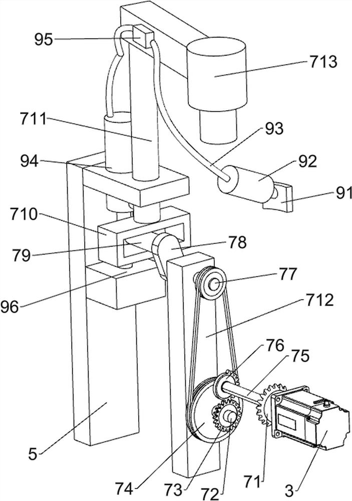
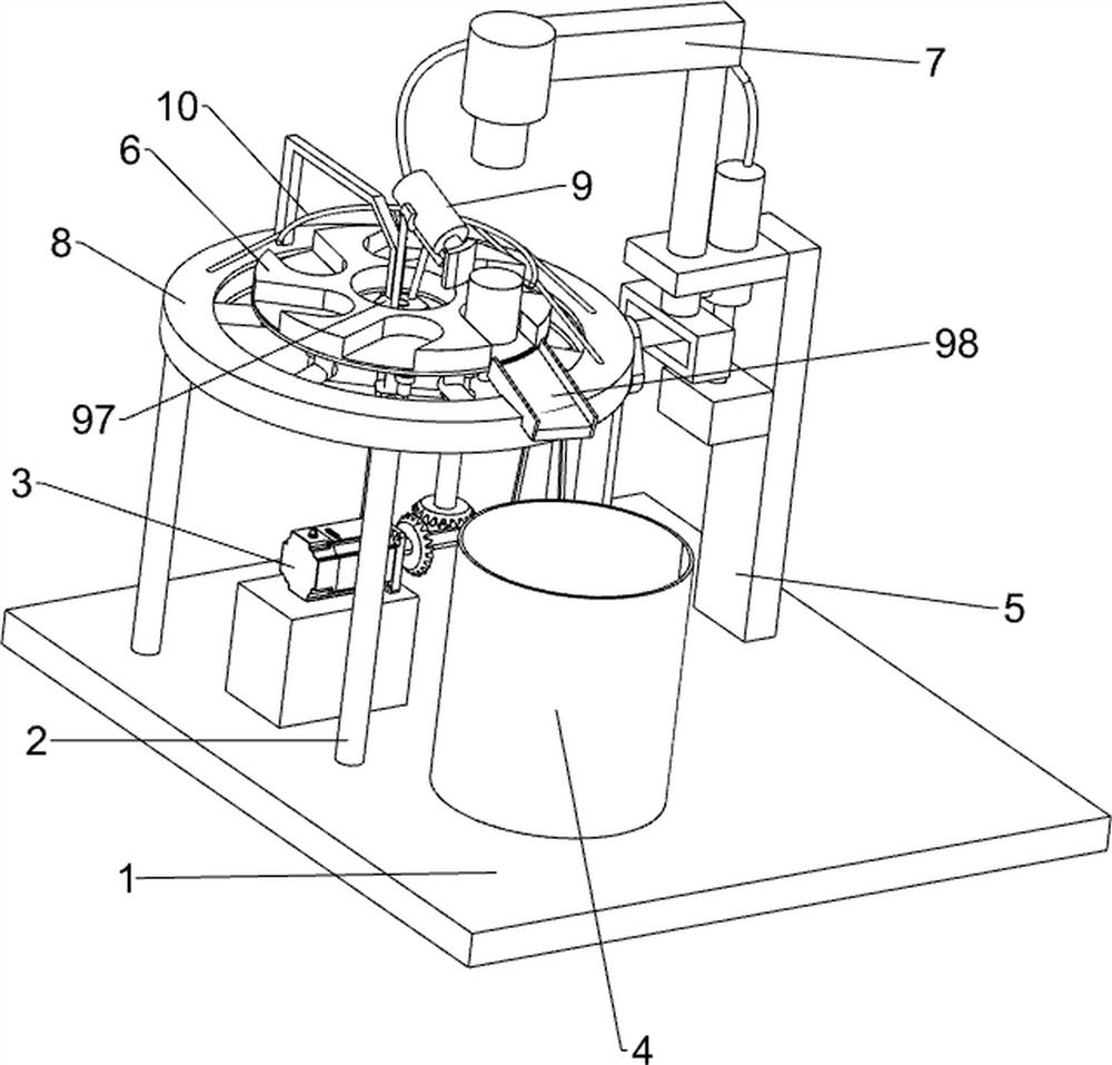
[0021] A kind of canned meat trademark printing device, such as figure 1 As shown, it includes a base 1, a first bracket 2, a servo motor 3, a finished product basket 4, a second bracket 5, a rotating mechanism 6, a lifting mechanism 7 and a circular slide rail 8, and the first bracket is uniformly arranged on the rear side of the top of the base 1 2. The number of the first support 2 is 4, the top of the first support 2 is connected with a ring slide rail 8, the servo motor 3 is provided on the left rear side of the top of the base 1, the finished product basket 4 is placed on the front side of the top of the base 1, and the base 1. A second bracket 5 is provided on the right rear side of the top, and a lifting mechanism 7 is connected to the second bracket 5. The parts of the lifting mechanism 7 are connected with the output shaft of the servo motor 3, and the rotating mechanism 6 is connected between the tops of the ring slide rails 8. The components of the swivel mechanism...

Embodiment 2

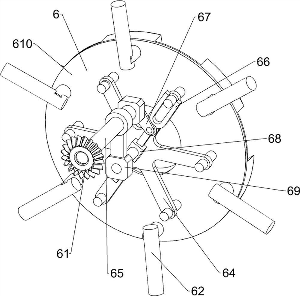
[0024] On the basis of Example 1, such as Figure 2-4 As shown, the rotating mechanism 6 includes a first bevel gear 61, a slide bar 62, a support frame 63, a turret 64, a first rotating shaft 65, a push rod 66, a rotating rod 67, a sliding sleeve 68, a fixed seat 69, and a rotating disk 610 , the bearing seat 611 and the fixed rod 612, the circular slide rail 8 is evenly connected with the slide bar 62 in the circumferential direction, the top of the slide bar 62 is connected with the rotating disk 610, and the middle side of the bottom of the rotating disk 610 is connected with the turret 64, wherein The tops of the three first brackets 2 are all provided with a support frame 63, and the support frame 63 is connected with a fixed seat 69, and the front part of the fixed seat 69 is connected with a bearing seat 611, and the bearing seat 611 is rotationally connected with the first rotating shaft 65. The bottom of a rotating shaft 65 is provided with a first bevel gear 61, the...

Embodiment 3

[0029] On the basis of Example 2, such as figure 1 and Figure 4 Shown, also include pusher mechanism 9, pusher mechanism 9 includes first piston 91, first cylinder body 92, connecting pipe 93, second cylinder body 94, fixed block 95, second piston 96, fixed mount 97 And the blanking plate 98, the bottom of the front side of the fixed rod 612 is connected with a fixed frame 97, the top of the fixed frame 97 is provided with a first cylinder 92, the right side of the first cylinder 92 is slidingly connected with a first piston 91, and the second support 5 A second cylinder 94 is provided on the rear side of the top, and a second piston 96 is provided at the bottom of the second cylinder 94. The second piston 96 is squeezed and fitted with the rectangular sliding sleeve 710, and a fixed block 95 is provided on the rear side of the left part of the stamp 713. A connecting pipe 93 is connected between the first cylinder body 92 and the second cylinder body 94, and the connecting ...


PUM


Abstract

The invention relates to a printing device, in particular to a meat can trademark printing device. According to the meat can trademark printing device provided by the invention, cans can be rotated and pressed, trademarks of the cans can be printed, and the cans can be automatically pushed out. The meat can trademark printing device comprises a base, first supports, an annular sliding rail, a servo motor, a second support, a lifting mechanism and a rotating mechanism, wherein the first supports are evenly arranged on the rear side of the top of the base; the annular sliding rail is connected between the tops of the first supports; the servo motor is arranged on the rear side of the top of the base; the second support is arranged on the side, close to the first supports, of the top of the base; the lifting mechanism is connected onto the second support; and the rotating mechanism is connected between the top of the annular sliding rail. Under the cooperation of the servo motor, a rotating mechanism, the lifting mechanism and a pushing mechanism, the effects of automatically rotating the cans, clamping the cans, carrying out trademark printing on the cans and automatically collectingthe cans subjected to trademark printing can be achieved through the meat can trademark printing device provided by the invention.

Description

technical field [0001] The invention relates to a printing device, in particular to a canned meat trademark printing device. Background technique [0002] Canned food refers to food made of materials that have been processed, canned, sealed and sterilized. Since canned food can be stored at room temperature for a long time, it can meet people's special needs for food under difficult conditions such as field hiking exploration, ocean voyage and mountaineering expeditions. There are many kinds of canned food, and the general factory will print the trademark on the top of the can after the canning is completed, for people's reference when purchasing. [0003] The existing canned trademark printing method is to manually use a stamp to print the canned trademark one by one. People fix the cans by hand, and then use the stamp to print the canned trademark. The operation steps of this canned trademark printing method are complicated and require manual The cans are fixed and the tr...

Claims


Application Information

Patent Timeline
Patent Type & Authority Applications(China)
IPC IPC(8): B41J3/407B41J11/00
CPCB41J3/4073B41J11/00
Inventor 彭芳东
Owner 彭芳东
Learn More