Self-rotating dustproof reversing camera

A camera and self-rotation technology, used in vehicle maintenance, image communication, vehicle components, etc., can solve the problems of seeing the rear of the vehicle, dust contamination, blurred camera acquisition, etc., to ensure clarity and maintain cleanliness.

Pending Publication Date: 2021-03-30
何金林
View PDF3 Cites 3 Cited by
  • Summary
  • Abstract
  • Description
  • Claims
  • Application Information

AI Technical Summary

Problems solved by technology

[0003] Since the reversing camera has been exposed for a long time, and the car will raise a lot of dust during driving, the raised dust will gather near the rear of the car. It is inevitable that some dust will contaminate the lens of the camera, resulting in blurred effects of camera acquisition. It is difficult for the driver to see the situation behind the car clearly through the camera. In severe cases, it will cause the driver to misjudge and easily cause dangerous accidents

Method used


Image

  • Self-rotating dustproof reversing camera
  • Self-rotating dustproof reversing camera
  • Self-rotating dustproof reversing camera

Examples


Embodiment 1

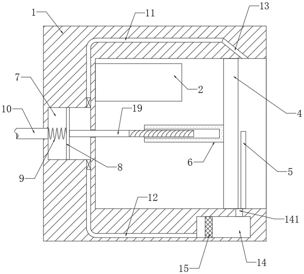
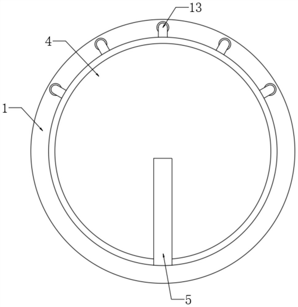
[0022] refer to Figure 1-2 , a self-rotating dust-proof reversing camera, including a lens barrel 1, a camera body 2 is installed in the lens barrel 1, a circular lens 4 is connected to the lens barrel 1 for rotation, and a brush plate is fixedly connected to the inner bottom of the lens barrel 1 5. The side wall of the lens 4 is fixedly connected with a threaded sleeve 6, and the internal thread of the threaded sleeve 6 is connected with a screw 19. The side wall of the lens barrel 1 is provided with an air intake slot 7, and a driving screw 19 is installed in the air intake slot 7 to reciprocate Mobile drives.

[0023] The driving device includes a piston 8 that is sealed and slidably connected in the air inlet groove 7, and the end of the screw rod 19 away from the threaded sleeve 6 is fixedly connected to the side wall of the piston 8. It should be noted that, as figure 1 As shown, the threaded part of the screw rod 19 is only distributed on a part of the screw rod 19 cl...

Embodiment 2

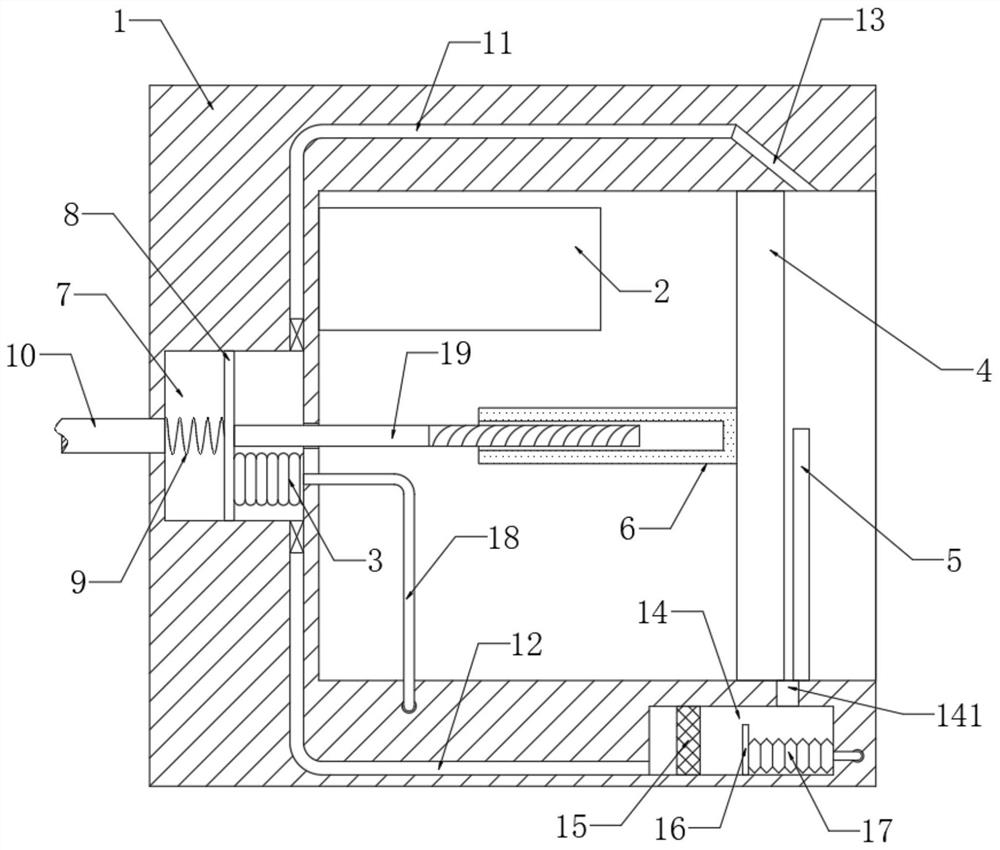
[0028] refer to image 3 , different from Embodiment 1, the clapper 16 is slidably connected in the dust storage tank 14, the side wall of the clapper 16 is fixedly connected with a telescopic air bag 17, and the end of the telescopic air bag 17 away from the clapper 16 is fixedly connected to the side wall of the dust storage tank 14 Above, the bellows 3 is fixedly connected between the piston 8 and the inner wall of the air intake groove 7 , and the bellows 3 communicates with the telescoping airbag 17 through the conduit 18 . It should be noted that both ends of the bellows 3 are blocked by the piston 8 and the inner wall of the air intake groove 7, which can ensure that the air can flow back and forth from the bellows 3 and the telescopic air bag 17 when the piston 8 moves back and forth.

[0029] In this embodiment, when the piston 8 moves back and forth in the air intake groove 7, it will continuously squeeze the bellows 3, blow the air in the bellows 3 into the telescop...


PUM


Abstract

The invention discloses a self-rotating dustproof reversing camera. The camera comprises a lens barrel, wherein a camera body is installed in the lens barrel, a circular lens is rotatably connected inthe lens barrel, a brush plate is fixedly connected to the inner bottom of the lens barrel, a threaded sleeve is fixedly connected to the side wall of the lens, and a screw rod is in threaded connection with the interior of the threaded sleeve; an air inlet groove is formed in the side wall of the lens barrel, a driving device for driving the screw to reciprocate is installed in the air inlet groove, the driving device comprises a piston connected into the air inlet groove in a sealed and sliding mode, and the end, away from the threaded sleeve, of the screw is fixedly connected to the side wall of the piston. According to the camera, the driving device is arranged to drive the screw to move back and forth so as to drive the circular lens to rotate back and forth, and the brush plate andthe lens move relatively, so the lens can be continuously cleaned to keep the cleanliness of the lens, and definition of the collection influence of the camera body is ensured.

Description

technical field [0001] The invention relates to the technical field of monitoring and camera-related equipment, in particular to a self-rotating dust-proof reversing camera. Background technique [0002] At present, when a car is reversing or turning around, it often relies on the reversing camera installed at the rear of the car to watch the situation behind the car, which is convenient for reversing and can prevent dangerous situations such as collisions. [0003] Since the reversing camera has been exposed for a long time, and the car will raise a lot of dust during driving, the raised dust will gather near the rear of the car. It is inevitable that some dust will contaminate the lens of the camera, resulting in blurred effects of camera acquisition. It is difficult for the driver to see the situation behind the car clearly through the camera, and in severe cases, it will cause the driver to misjudge and easily cause dangerous accidents. Contents of the invention [00...

Claims


Application Information

Patent Timeline
Patent Type & Authority Applications(China)
IPC IPC(8): B60R11/04B60S1/56H04N5/225
CPCB60R11/04B60S1/566H04N23/51H04N23/50
Inventor 何金林
Owner 何金林
Why Eureka
Try Eureka