Power cable laying device

A technology for laying devices and power cables, applied in cable laying equipment, transportation and packaging, thin material handling, etc., can solve the problems of long wires and cables, unstable device operation, etc.

Active Publication Date: 2021-03-30
国网河南省电力公司方城县供电公司
View PDF14 Cites 3 Cited by
  • Summary
  • Abstract
  • Description
  • Claims
  • Application Information

AI Technical Summary

Problems solved by technology

However, because the wires and cables to be laid are often relatively long and the cables rub against the winding part of the device during the unwinding process, the device will run unstable due to the drag of the cable or the friction between the device and the device.

Method used


Image

  • Power cable laying device
  • Power cable laying device
  • Power cable laying device

Examples


Embodiment Construction

[0021] The following will clearly and completely describe the technical solutions in the embodiments of the present invention with reference to the accompanying drawings in the embodiments of the present invention. Obviously, the described embodiments are only some, not all, embodiments of the present invention. Based on the embodiments of the present invention, all other embodiments obtained by persons of ordinary skill in the art without making creative efforts belong to the protection scope of the present invention.

[0022] It should be noted that if there is a directional indication (such as up, down, left, right, front, back...) in the embodiment of the present invention, it is only used to explain the relationship between the components in a certain posture. If the specific posture changes, the directional indication will also change accordingly.

[0023] In addition, if the descriptions of "first", "second", etc. are involved in the present invention, they are only use...


PUM


Abstract

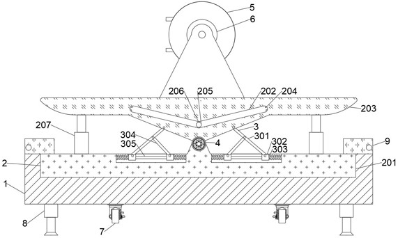
The invention discloses a power cable laying device. The power cable laying device comprises a base, an adjusting mechanism is arranged above the base, the adjusting mechanism comprises a mounting block and a balance plate rotationally connected to the mounting block, the bottom of the balance plate is conical, and a V-shaped closed sliding groove is further formed in the balance plate. Two firstelectrode plates which are not in contact with each other are arranged at the two ends of the sliding groove separately, two second electrode plates which are not in contact with each other are arranged at the bottom of the sliding groove, and a metal ball capable of freely rolling in the sliding groove is further arranged in the sliding groove. Electric telescopic rods corresponding to the firstelectrode plates on the side are arranged on the two sides of the bottom of the balance plate. A locking mechanism is arranged at the joint of the balance plate and the mounting block. Compared with atraditional device, the power cable laying device is higher in stability.

Description

technical field [0001] The invention relates to the technical field of power equipment, in particular to a power cable laying device. Background technique [0002] Power cables are cables used to transmit and distribute electrical energy, and are often used in urban underground power grids and internal power supply of enterprises. In the process of electric power construction, it is often necessary to lay cables to realize the function of power supply in different areas. At present, the existing wire and cable laying device needs to put the cable into the trench dug in advance while moving. But because the wires and cables that need to be laid are often relatively long and the cable generates friction with the winding part of the device during the process of releasing, the device will cause unstable operation of the device due to the drag of the cable or the friction generated between the device. Contents of the invention [0003] The purpose of the present invention is ...

Claims


Application Information

Patent Timeline
Patent Type & Authority Applications(China)
IPC IPC(8): B65H49/20B65H49/36H02G1/06
CPCB65H49/20B65H49/36H02G1/06
Inventor 周露马宁赵朔贾明磊李政袁航侯威杜娟
Owner 国网河南省电力公司方城县供电公司
Why Eureka
Try Eureka