

High-safety steel structure supporting beam structure for building
A safety and steel structure technology, applied in the field of building steel structure, can solve the problems of supporting beam weight, reducing work efficiency, inconvenient transportation of supporting beams, etc.
- Summary
- Abstract
- Description
- Claims
- Application Information
AI Technical Summary
Problems solved by technology
Method used
Image

Examples
Embodiment Construction
[0027] The following will clearly and completely describe the technical solutions in the embodiments of the present invention with reference to the accompanying drawings in the embodiments of the present invention. Obviously, the described embodiments are only some, not all, embodiments of the present invention. Based on the embodiments of the present invention, all other embodiments obtained by persons of ordinary skill in the art without making creative efforts belong to the protection scope of the present invention.
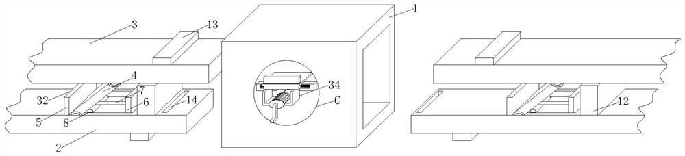
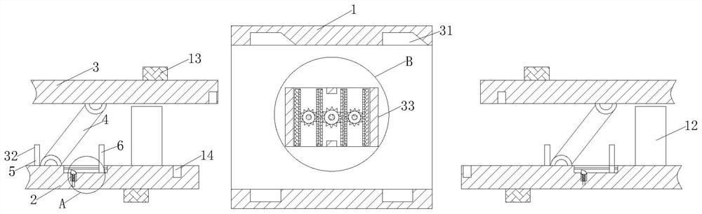
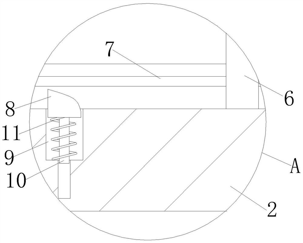
[0028] see Figure 1-5 , a steel structure support beam structure with high safety for construction, including a connection box 1, the two sides of the connection box 1 are respectively provided with a bottom beam plate 2 and a top beam plate 3, and the bottom beam plate 2 and the top beam plate The connecting plate 4 is movable between the beams 3, the surface of the bottom beam 2 is provided with a limiting mechanism 32, the inside of the connecting box 1 is...
PUM
 Abstract
Description
Claims
Application Information