
Indoor dust collection and humidification module

A technology for vacuuming holes and dust, applied in the field of indoor cleaning devices, can solve the problems of furniture dead corners that cannot function well, no substantive solutions, easy to cause respiratory diseases, etc., so as to inhibit the rise of indoor dust and reduce The input of manpower and the effect of avoiding indoor drying

Inactive Publication Date: 2021-03-30
HARBIN ENG UNIV
View PDF10 Cites 0 Cited by
  • Summary
  • Abstract
  • Description
  • Claims
  • Application Information

AI Technical Summary

Problems solved by technology

[0002] In a relatively closed room, it is easy to gather dust, and most of the dust is concentrated in the dead corner of the space, which is very inconvenient to clean. If the dust is not cleaned in time, it is easy to cause respiratory diseases over time
For indoor dust removal, ordinary vacuum cleaners can't play a good role in some dead corners of furniture, and the improvement of vacuum cleaners obviously cannot fundamentally solve this problem
And for the dust suspended in the air, there is no good solution yet
At the same time, there is still no substantive solution to the situation of dust rising and indoor drying caused by floor heating

Method used


Image

  • Indoor dust collection and humidification module
  • Indoor dust collection and humidification module
  • Indoor dust collection and humidification module

Examples


Embodiment Construction

[0019] The present invention is described in more detail below in conjunction with accompanying drawing example:

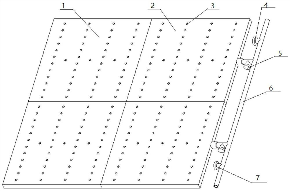
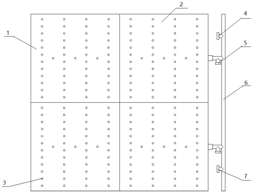
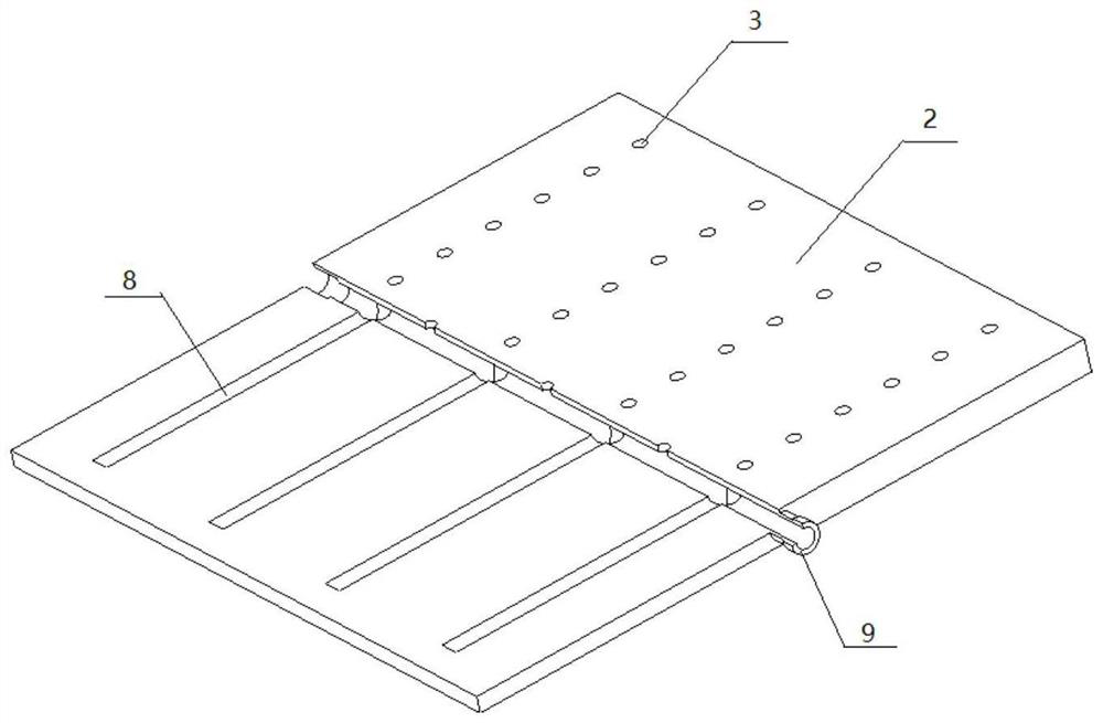
[0020] combine Figure 1-5 , an indoor vacuuming and humidifying module of the present invention, comprising a tail tile 1, a middle tile 2, and a main pipeline 6, the tail tile 1 and the middle tile 2 are connected through an O-ring 9, the main pipeline 6 is connected to the middle tile 2, and the main pipeline One end of the water blocking valve 7 of the road 6 is connected to an air extraction device, and one end of the blocking valve 4 is connected to the water supply device.

[0021] Internal pipelines 8 are provided in the rear tile 1 and the middle tile 2 . The tail tile 1 and the middle tile 2 are provided with circular suction holes 3 . A liquid level gauge 10 is arranged on the tail tile 1 . The tail tile 1 and the middle tile 2 are connected by an O-ring 9 . The main pipeline 6 is provided with a branch valve 5 , an air blocking valve 4 and a water ...


PUM


Abstract

The invention aims to provide an indoor dust collection and humidification module. The indoor dust collection and humidification module comprises a tail ceramic tile, a middle ceramic tile and a mainpipeline, wherein a tail ceramic tile water supply pipeline and a tail ceramic tile internal pipeline are arranged in the tail ceramic tile, tail ceramic tile dust collection holes are arranged in thesurface of the tail ceramic tile, and a tail ceramic tile O-shaped ring is arranged at the end of the tail ceramic tile water supply pipeline; a middle ceramic tile water supply pipeline and a middleceramic tile internal pipeline are arranged in the middle ceramic tile, middle ceramic tile dust collection holes are arranged in the surface of the middle ceramic tile, and a middle ceramic tile O-shaped ring is arranged at the end of the middle ceramic tile water supply pipeline; the tail ceramic tile and the middle ceramic tile are connected through the tail ceramic tile O-shaped ring and themiddle ceramic tile O-shaped ring; and the main pipeline is connected to the middle ceramic tile water supply pipeline, a branch valve is arranged at the joint of the main pipeline and the middle ceramic tile water supply pipeline, and a choke valve and a water blocking valve are arranged on the main pipeline. According to the indoor dust collection and humidification module, the situation that indoor dust rises due to floor heating can be well restrained, the flow of inlet and outlet water can be adjusted, and therefore the indoor space is humidified.

Description

technical field [0001] The invention relates to an indoor cleaning device. Background technique [0002] In a relatively closed room, it is easy to gather dust, and most of these dusts are concentrated in the dead corners of the space, which is very inconvenient to clean. If the dust is not cleaned in time, it is easy to cause respiratory diseases over time. For indoor dust removal, ordinary vacuum cleaners can't play a good role in the dead corners of some furniture, and the improvement of vacuum cleaners obviously cannot fundamentally solve this problem. And for the dust suspended in the air, there is no good solution yet. At the same time, there is still no substantive solution to the situation of dust rising and indoor drying when using floor heating. Contents of the invention [0003] The purpose of the present invention is to provide an indoor dust collection and humidification module with functions of dust collection and humidification. [0004] The purpose of th...

Claims


Application Information

Patent Timeline
IPC IPC(8): F24F6/00F24F11/72
CPCF24F6/00F24F11/72
Inventor 王忠义王瑞浩张力敏万雷王萌王艳华栾一刚孙涛曲永磊
Owner HARBIN ENG UNIV
Learn More