A relay test fixture

A technology for testing fixtures and fixtures, which is applied in the field of fixtures, and can solve the problems of inconvenient device interface dustproofing, long debugging time, and increased false detection rate, so as to prevent poor connection, solve inaccurate alignment, and increase stability sexual effect

Active Publication Date: 2022-03-15
苏州市高威电子有限公司
View PDF0 Cites 0 Cited by
  • Summary
  • Abstract
  • Description
  • Claims
  • Application Information

AI Technical Summary

Problems solved by technology

[0004] Aiming at the deficiencies of the prior art, the present invention provides a relay test fixture, which solves the problem of needle transfer, increased mismeasurement rate, difficult alignment, long debugging time, and the A / B mold needs to be done again. It is not convenient for the device interface to be dust-proof, it is not convenient to prevent the connection of the device from falling off, it is not convenient to prevent the device from slipping, and it is not convenient to disassemble and replace the parts of the device

Method used


Image

  • A relay test fixture
  • A relay test fixture
  • A relay test fixture

Examples


Embodiment

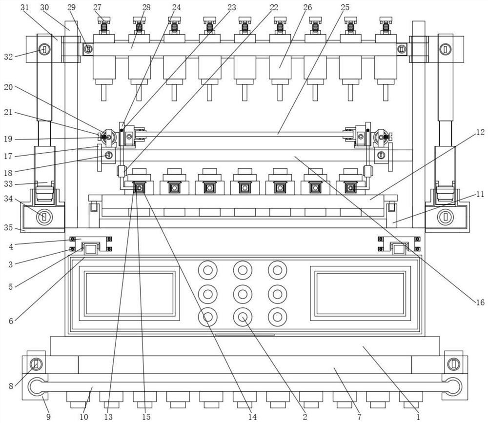
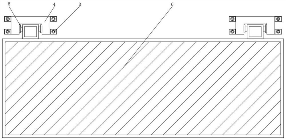
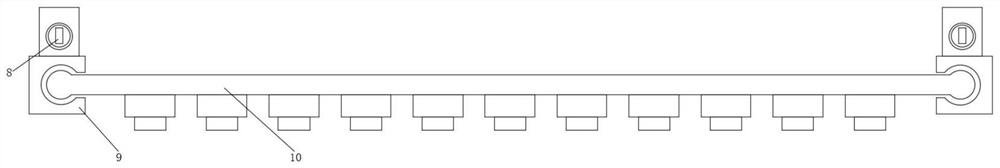
[0030] see Figure 1-6 , in this embodiment: a relay test fixture, including a fixture table 1 and a fixture reel 11, a control switch 2 is installed on the inside of the fixture table 1, and a first positioning rod is connected to the front of the control switch 2 3. The first connecting block 4 is connected to the outer side of the first positioning rod 3, and the first rotating shaft 5 is installed on the inner side of the first connecting block 4, and the protective cover 6 is arranged under the first rotating shaft 5, and the protective cover 6 A base 7 is installed, the two ends of the base 7 are connected with a second positioning rod 8, and the outside of the second positioning rod 8 is connected with a second connecting block 9, and the inner side of the second connecting block 9 is connected with a non-slip soft rubber strip 10 , the jig reel 11 is installed above the control switch 2, and the test lower mold 12 is installed above the jig reel 11, the front of the te...


PUM


Abstract

The present invention belongs to the field of jig-related technologies, in particular to a relay test jig, comprising a jig table and a jig reel, a control switch is installed inside the jig table, and a first switch is connected to the front of the control switch. Positioning rod, the first connecting block is connected to the outside of the first positioning rod, and the first rotating shaft is installed on the inside of the first connecting block, a protective cover is arranged under the first rotating shaft, and a protective cover is installed under the protective cover The base, the two ends of the base are connected with the second positioning rod, and the outside of the second positioning rod is connected with the second connecting block, the present invention plays a thread fixing role on the adapter block by setting the fifth positioning rod, in use When installing, the setting of the transfer block is convenient for testing the device. The number of equipment points is insufficient, and it is convenient to transfer from top to bottom, or from bottom to top. , which improves the efficiency of installing fixtures and reduces false detection.

Description

technical field [0001] The invention relates to the related technical field of jigs, in particular to a relay test jig. Background technique [0002] Printed circuit boards have been widely used and demanded in the fields of aerospace, military, mobile communications, laptops, computers, digital cameras, tablet computers, wearable electronic devices, high-speed printer heads, etc., suitable for notebook computers, automotive printing Circuit products; the application fields of this circuit board mainly cover: civil electronic products, telecommunications, high-frequency control equipment, LED, automotive fields, etc. Specifically, such as: electronic equipment, notebook computers, computer cases, mobile phones, base stations, telecommunication equipment, electric power, railways and other electronic equipment with harsh environments. At present, the accuracy of printed circuit boards is getting higher and higher, and the number of points is increasing. The points of the fix...

Claims


Application Information

Patent Timeline
Patent Type & Authority Patents(China)
IPC IPC(8): G01R31/28
CPCG01R31/2808
Inventor 苏军梅
Owner 苏州市高威电子有限公司
Why Eureka
Try Eureka