Anti-humpback student desk with adjustable backrest
An anti-hunchback and adjustable technology, applied in the field of student desks, can solve the problems of students keeping, books fixed on desks, and the angle of desks cannot be adjusted, so as to achieve simple operation, high adjustment efficiency, and avoid hunchback. Effect
- Summary
- Abstract
- Description
- Claims
- Application Information
AI Technical Summary
Problems solved by technology
Method used
Image
Examples
Embodiment 1
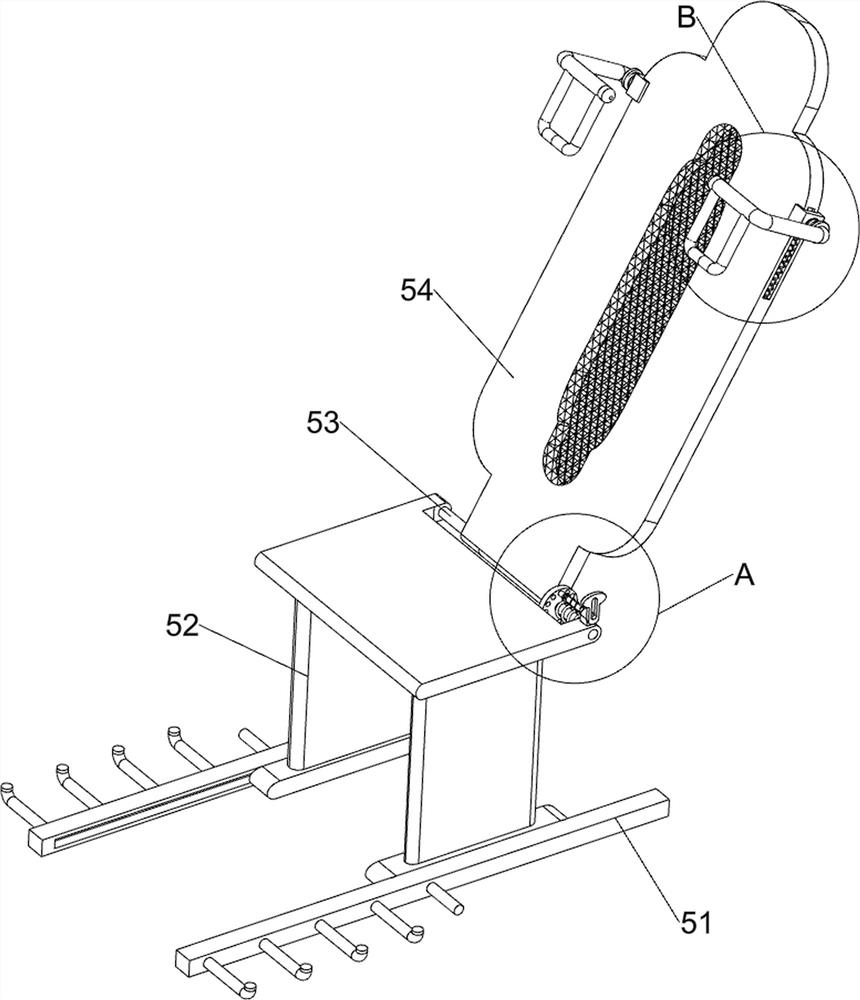
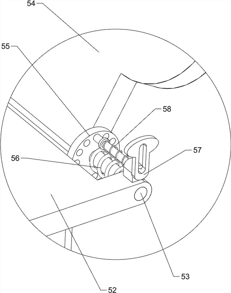
[0029] An adjustable backrest anti-hunchback student desk, such as Figure 1 to Figure 5 As shown, it includes base 1, telescopic rod 2, fastening bolt 21, storage box 3, barrier mechanism 4 and backrest mechanism 5, four telescopic rods 2 are installed on the top of base 1, and telescopic rod 2 is threadedly connected with Tightening bolt 21, storage box 3 is connected between the tops of four telescopic rods 2, the right side of storage box 3 is equipped with blocking mechanism 4, and base 1 right side is equipped with backrest mechanism 5.
[0030] The blocking mechanism 4 includes a first guide slide frame 41, a baffle plate frame 42, a block 43, a first guide rod 44 and a first spring 45, and the right end middle part of the storage box 3 is connected with the first guide slide frame 41, the second A baffle frame 42 is slidably connected to a guide carriage 41, and a first guide rod 44 is slidably connected to the bottom of the baffle frame 42, and a block 43 is connected...
Embodiment 2
[0034] On the basis of Example 1, such as Figure 7 and Figure 8 Shown, also comprise lifting mechanism 6, and lifting mechanism 6 comprises the 3rd guide slide frame 61, the first support frame 62, top plate 63, guide block 64, the 3rd guide rod 65, the 3rd spring 66 and pull bar 67, base 1 The middle parts of the front and rear sides are connected with the third guide frame 61, the upper parts of the four telescopic rods 2 are connected with the first support frame 62, and the top plate 63 is connected between the four first support frames 62, and the front and rear of the top plate 63 Both sides are slidably connected with a third guide rod 65, the tail end of the third guide rod 65 is connected with a guide block 64, the guide block 64 cooperates with the third guide carriage 61, and the first guide block 64 is connected with the top plate 63. Three springs 66, and a pull rod 67 connected to the bottom of the guide block 64.
[0035] At first, all the fastening bolts 21 a...
Embodiment 3
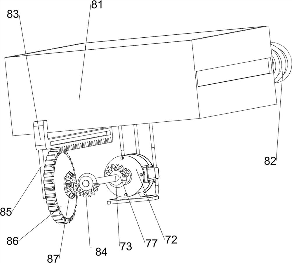
[0039] On the basis of Example 2, such as Figure 6 and Figure 9 As shown, the opening and closing mechanism 8 is also included, and the opening and closing mechanism 8 includes a drawer 81, a fourth spring 82, a second rack 83, a second missing tooth bevel gear 84, a third support frame 85, and a second spur gear 86 and the second bevel gear 87, the front side of the storage box 3 is slidingly connected with a drawer 81, the rear end of the drawer 81 and the storage box 3 are connected with a fourth spring 82, and the bottom of the storage box 3 is sliding on the left side. The ground is connected with a second rack 83, the front end of the second rack 83 is connected with the front wall of the drawer 81, the front end of the rotating shaft 73 is connected with a second bevel gear 84 with missing teeth, and the bottom front side of the storage box 3 is connected with a third gear. The support frame 85, the third support frame 85 is rotatably connected with a second spur gea...
PUM
 Abstract
Description
Claims
Application Information
 - R&D
- Intellectual Property
- Life Sciences
- Materials
- Tech Scout
- Unparalleled Data Quality
- Higher Quality Content
- 60% Fewer Hallucinations
Browse by: Latest US Patents, China's latest patents, Technical Efficacy Thesaurus, Application Domain, Technology Topic, Popular Technical Reports.
© 2025 PatSnap. All rights reserved.Legal|Privacy policy|Modern Slavery Act Transparency Statement|Sitemap|About US| Contact US: help@patsnap.com


