Flue gas treatment system

A flue gas treatment system and flue gas technology, applied in the direction of separation methods, dispersed particle separation, chemical instruments and methods, etc., can solve problems such as pipeline Louis ash transportation compensation, etc., to improve service life, improve ash transportation efficiency, and adaptability strong effect

Active Publication Date: 2022-06-24
安化华晟生物能源有限责任公司
View PDF7 Cites 1 Cited by
  • Summary
  • Abstract
  • Description
  • Claims
  • Application Information

AI Technical Summary

Problems solved by technology

[0004] The invention provides a flue gas treatment system to solve the technical problem of compensation for ash transport in pipes and roads existing in the existing flue gas treatment system

Method used


Image

  • Flue gas treatment system
  • Flue gas treatment system

Examples


Embodiment Construction

[0024] The embodiments of the present invention will be described in detail below with reference to the accompanying drawings, but the present invention can be implemented in many different ways as defined and covered below.

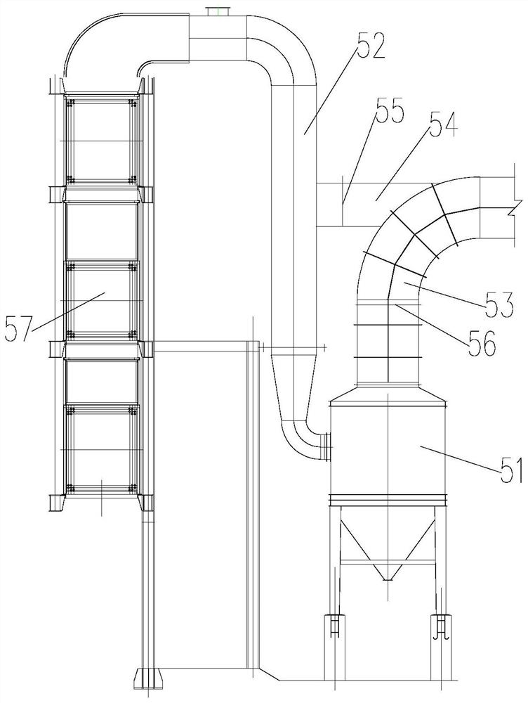
[0025] refer to figure 1 , a preferred embodiment of the present invention provides a flue gas treatment system, including: an inertial separator 51 for inertial separation of flue gas, a bag dust removal system for bag dust removal of flue gas, and the inertial separator 51. The air inlet is communicated with an air intake flue 52, the air inlet of the air intake flue 52 is communicated with the exhaust end of the boiler, and the air outlet of the inertial separator 51 is communicated with an exhaust flue 53. The exhaust port is connected to the bag dust removal system. The flue gas treatment system also includes a short-circuit bypass flue 54 for connecting the intake flue 52 and the exhaust flue 53, and the two ends of the short-circuit bypass flue 5...


PUM


Abstract

The invention discloses a flue gas treatment system, comprising: an inertial separator and a bag dust removal system, the air inlet of the inertial separator is connected with an air inlet flue, and the air inlet of the air inlet flue is connected with the smoke exhaust end of a boiler , the exhaust port of the inertia separator is connected with the exhaust flue, and the exhaust port of the exhaust flue is connected with the bag filter system. The flue gas treatment system also includes a short-circuit bypass flue for connecting the intake flue and the exhaust flue. A first opening adjustment device for controlling the flow area of ​​the bypass flue is provided. The exhaust flue is provided with a second opening adjustment device for controlling the size of its flow area, and the second opening adjustment device is located upstream of the position where the bypass flue communicates with the exhaust flue. The flue gas treatment system of the present invention can make the separation and dust removal of the flue gas flexible and controllable, and solve the technical problem of poor ash transportation in the pipeline of the flue gas treatment system.

Description

technical field [0001] The present invention relates to the technical field of biological generator sets, in particular, to a flue gas treatment system. Background technique [0002] In the biological generator set, the stove is connected with a flue, and the flue gas generated by the combustion of biomass fuel in the stove enters the flue. The role of the filter, the coarser soot enters the multi-tube dust collector, and the finer soot enters the bag filter, and the soot in the bag filter is separated by the bag filter, and the finer soot directly passes through the flue. It is discharged into the air, while the coarse soot is retained in the bag filter, and the soot retained in the bag filter and the soot in the multi-tube filter are transported into the ash storage by the ash conveying system. [0003] In the prior art, the flue gas treatment system formed by the connection of the inertial separator, the bag filter, and the multi-tube dust collector is prone to poor tran...

Claims


Application Information

Patent Timeline
Patent Type & Authority Patents(China)
IPC IPC(8): B01D50/20
CPCB01D50/20
Inventor 王热华贾星亮贾奥万为华王熙福黄军王熙毅
Owner 安化华晟生物能源有限责任公司
Why Eureka
Try Eureka