Supercharge Your Innovation With Domain-Expert AI Agents!

Cable shearing mechanism with adjustable shearing length

A cutting mechanism and cable technology, which is applied in the field of cable cutting devices, can solve problems such as the inability to meet the cutting needs of cables of different lengths, and achieve the effects of preventing deviation, increasing cutting speed, and controlling precision

Pending Publication Date: 2021-04-02
国网浙江省电力有限公司开化县供电公司
View PDF9 Cites 0 Cited by
  • Summary
  • Abstract
  • Description
  • Claims
  • Application Information

AI Technical Summary

Problems solved by technology

The cutting device adjusts the gap between the extrusion pad and the cable by rotating the screw, which ca

Method used


Image

  • Cable shearing mechanism with adjustable shearing length
  • Cable shearing mechanism with adjustable shearing length
  • Cable shearing mechanism with adjustable shearing length

Examples


Example Embodiment

[0052]Example 1

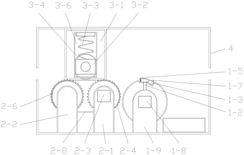
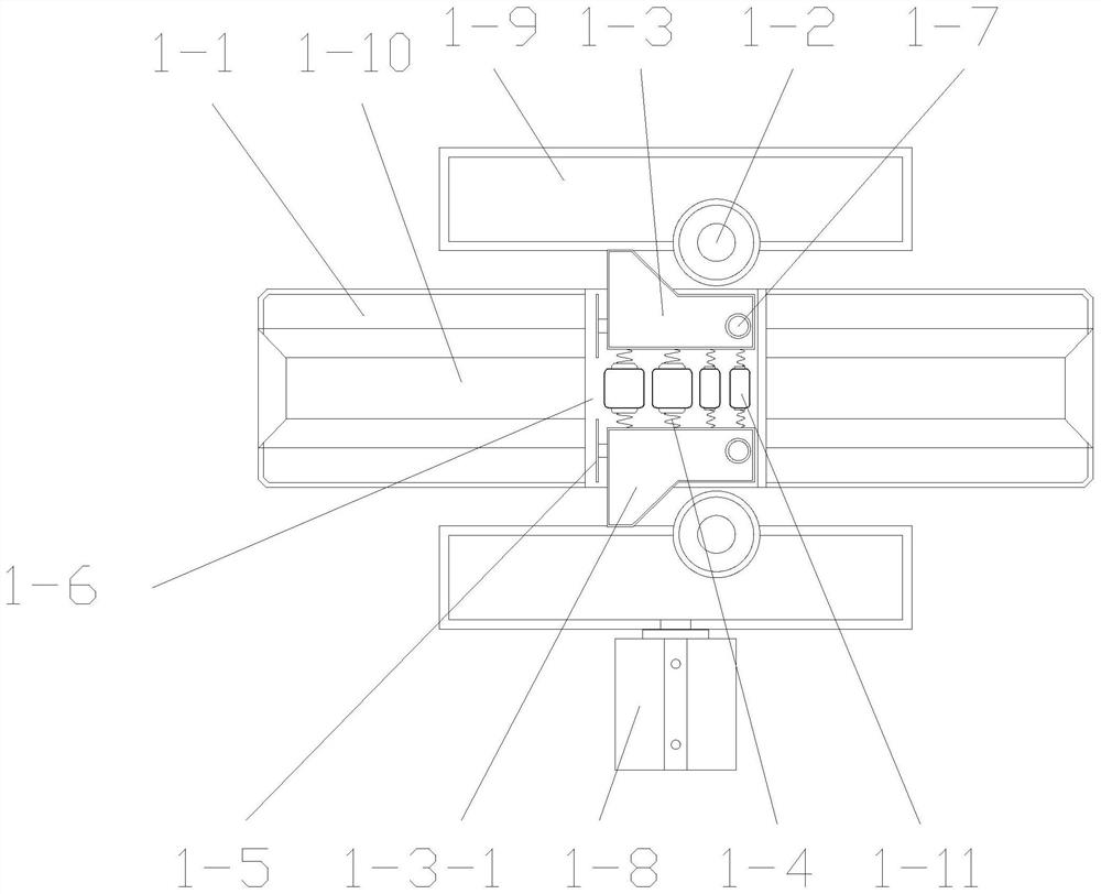
[0053]Cable shear mechanism adjustable with shear length, such asfigure 1 withFigure 3 ~ 5As shown, two first support columns 1-9, first rotating electric machine 1-8, shear wheel 1-1, two limit cylinders 1-2, clamping assembly, two blades 1-5, two Second Rotary Motor 1-13, four roller rollers 1-11; the clamping assembly includes two fixed cylinders 1-7, two connecting blocks 1-3, and the first retractable member 1-4. Two first support columns 1-9 are set inside and outside (pressfigure 1 The orientation shown), and the lower end is fixed to the bottom of the inner wall of the outer frame 4. The first rotating electric machine 1-8 is provided on one of the first support columns 1-9; the shear wheel 1-1 is axially connected to the rotation shaft of the first rotating electric machine 1-8, and is located in two first support columns 1 -9 between. There is a gap 1-6 on the circumferential surface of the shear wheel 1-1; the circumference of the shear wheel 1-1 is provide...

Example Embodiment

[0058]Example 2

[0059]The difference from the first embodiment is that the limit cylindrical 1-2 is rotated by rotating the connection to the first support column 1-9 to achieve the rotation of the limit cylinder 1-2.

[0060]During the limit cylinder 1-2 clamps the opposing two connection blocks 1-3 by extrusion, the rotation of the limit cylinder 1-2 can reduce the friction between the connecting blocks 1-3, so It can reduce the wear of both, while also preventing the rotation of the shear wheel 1-1 causes hindrance.

Example Embodiment

[0061]Example 3

[0062]The difference from the first embodiment is that the equal spacing at the circumferential surface of the shear wheel 1-1 is provided with two gaps 1-6, and a set of clamp assemblies are provided in each of the notches 1-6. The total number of blades 1-5 and the second rotating electric machine 1-13 is four, and the total number of the roller 1-11 is eight.

[0063]Two gaps 1-6 are provided by equal spacing, and the shear wheel 1-1 rotates two shears, and the speed of the shear wheel 1-1 can be reduced in the case of the desired cable shear length. Thereby, thereby reducing the energy consumption during the running of the first rotating motor 1-8.


PUM


Abstract

The invention relates to the field of cable shearing devices, and discloses a cable shearing mechanism with an adjustable shearing length. The cable shearing mechanism comprises a shearing wheel, at least two limiting cylinders respectively located on the two sides of the shearing wheel, at least one set of clamping assembly arranged in the circumferential direction of the shearing wheel and rotating along with the shearing wheel, and blades connected with the clamping assembly, wherein the clamping assembly is clamped by the interference of the limiting cylinders in the process of rotating along with the shearing wheel, and then the blades are driven to cut off a cable. According to the cable shearing mechanism, the shearing length of the cable can be controlled by controlling the rotating speed of the shearing wheel.

Description

technical field [0001] The invention relates to the field of cable cutting devices, in particular to a cable cutting mechanism with adjustable cutting length. Background technique [0002] The relay is an electrical control device, which is an electrical appliance that causes the controlled quantity to undergo a predetermined step change in the electrical output circuit when the change of the input quantity meets the specified requirements. It has an interactive relationship between the control system and the controlled system. Usually used in automatic control circuits, it is actually an "automatic switch" that uses a small current to control the operation of a large current. Therefore, it plays the role of automatic adjustment, safety protection, and conversion circuit in the circuit. [0003] Existing cable cutting devices are usually unable to automatically adjust the cut length of each section of cable, making it difficult to adapt to different cutting requirements. ...

Claims


Application Information

Patent Timeline
IPC IPC(8): B21F11/00B21F23/00
CPCB21F11/00B21F23/00Y02W30/82
Inventor 鲁晨浩陈志军张耀胡晓波管仙美毛芹伟陈松常亮李一林邓东星石程烨殷一般陈冬馨徐远征郑斌
Owner 国网浙江省电力有限公司开化县供电公司
Features
  • R&D
  • Intellectual Property
  • Life Sciences
  • Materials
  • Tech Scout
  • Unparalleled Data Quality
  • Higher Quality Content
  • 60% Fewer Hallucinations
Learn More