

Fuel Distribution in Multi-Fuel Tank Compressed Gas Fuel Systems
- Summary
- Abstract
- Description
- Claims
- Application Information
AI Technical Summary
Benefits of technology
Problems solved by technology
Method used
Image

Examples
Embodiment Construction
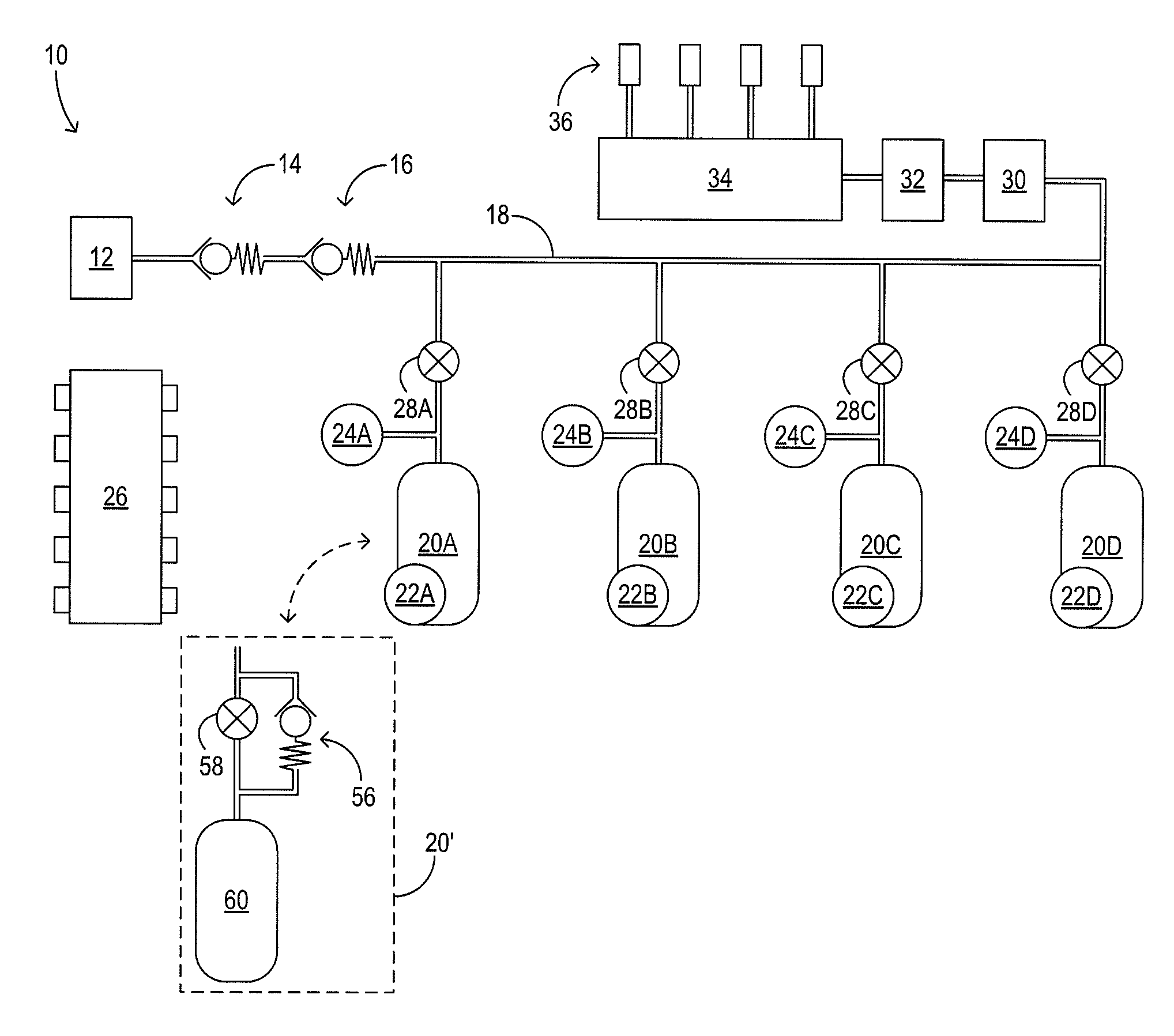
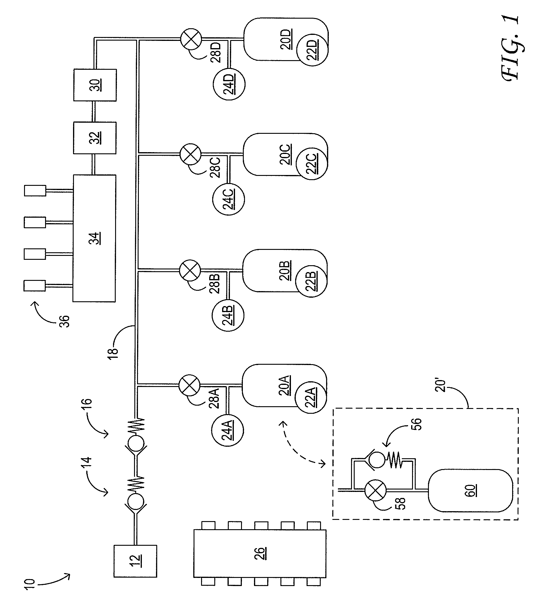
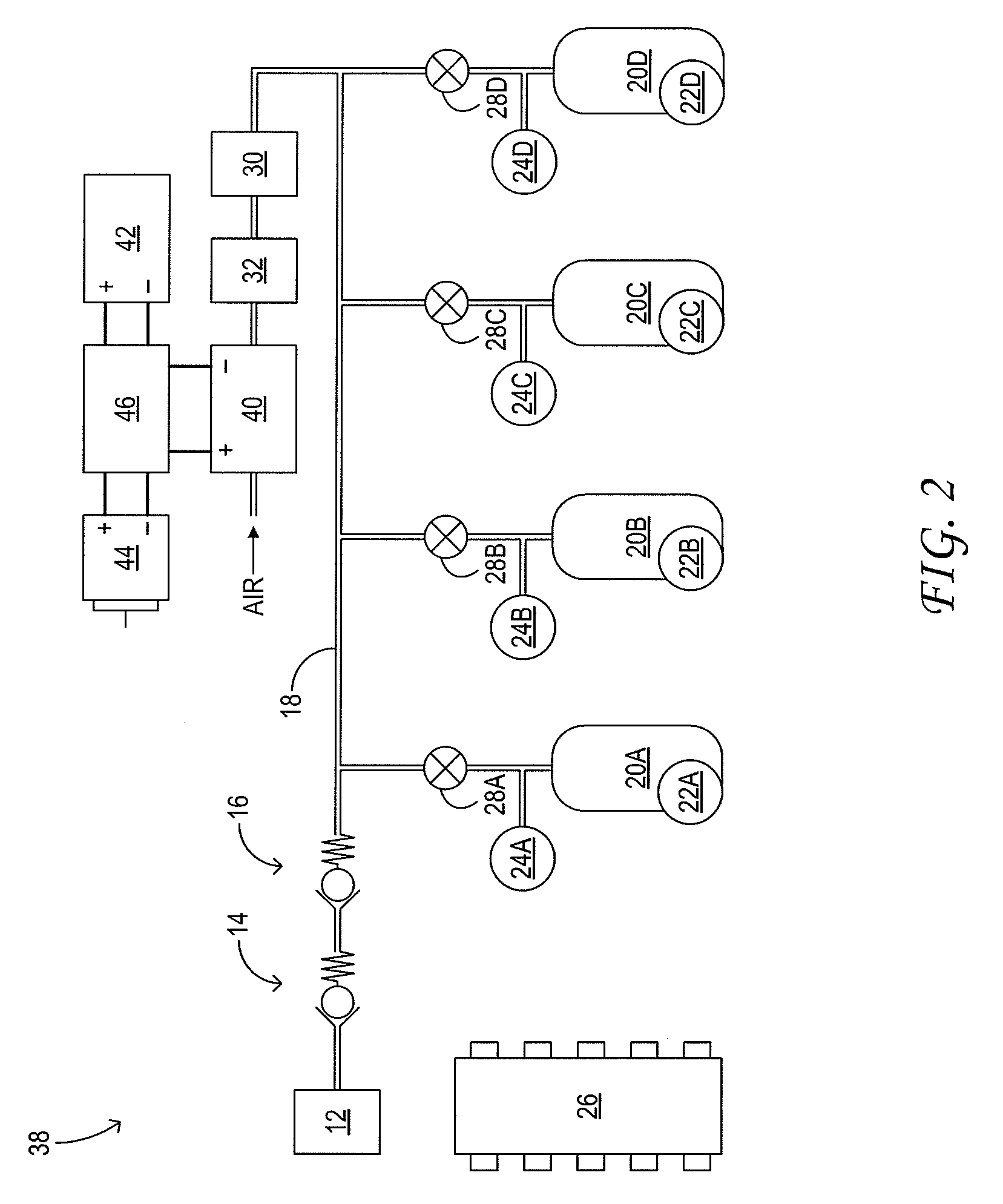
[0014]The subject matter of the present disclosure is now described by way of example and with reference to certain illustrated embodiments. Components that may be substantially the same in two or more embodiments are identified coordinately and are described with minimal repetition. It will be noted, however, that components identified coordinately in different embodiments of the present disclosure may be at least partly different. It will be further noted that the drawings included in this disclosure are schematic. Views of the illustrated embodiments are generally not drawn to scale; aspect ratios, feature size, and numbers of features may be purposely distorted to make selected features or relationships easier to see.
[0015]FIG. 1 schematically shows aspects of an example fuel system 10 configured to distribute fuel among a plurality of fuel tanks. The fuel system may be installed in a motor vehicle. In the illustrated embodiment, pressurized, gaseous fuel is admitted to the fuel...
PUM
| Property | Measurement | Unit |
|---|---|---|
| Temperature | aaaaa | aaaaa |
| Pressure | aaaaa | aaaaa |
Abstract
Description
Claims
Application Information