Multi-stage control device and method for dynamic tension of optical fiber winding machine

A technology of a control device and a control method, applied in the field of optical fiber winding, can solve the problems of inability to quickly and accurately control the optical fiber tension, inability to accurately adjust the optical fiber tension, single change of the speed of the pay-off wheel, etc. Powerful effect

Inactive Publication Date: 2016-07-27
NORTH CHINA UNIVERSITY OF TECHNOLOGY
View PDF8 Cites 27 Cited by
  • Summary
  • Abstract
  • Description
  • Claims
  • Application Information

AI Technical Summary

Problems solved by technology

However, adjusting the tension of the optical fiber by changing the speed of the pay-off wheel cannot precisely adjust the tension of the optical fiber, and the tension system with a tension sensor has a large number of pulleys, which increases the friction with the optical fiber and seriously affects the tension measurement of the optical fiber
[0006] It can be seen that during

Method used


Image

  • Multi-stage control device and method for dynamic tension of optical fiber winding machine
  • Multi-stage control device and method for dynamic tension of optical fiber winding machine
  • Multi-stage control device and method for dynamic tension of optical fiber winding machine

Examples


Embodiment Construction

[0030] Preferred embodiments of the present invention will be described in detail below in conjunction with the accompanying drawings.

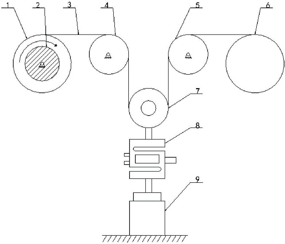
[0031] refer to figure 1 , the preferred embodiment of the present invention provides a multi-stage dynamic tension control device for optical fiber winding machine, including a pay-off wheel 1 and a take-up ring 6, and also includes a guide wheel A4 and a guide wheel B5, the pay-off wheel 1, the guide wheel A4, the guide wheel B5 is fixedly arranged successively from left to right, and the take-up ring can be movably arranged at the right end, and a tensioning wheel 7 that can move up and down is arranged between the guiding wheel A4 and the guiding wheel B5, and the tensioning wheel 7 The lower part is fixedly connected with a pull pressure sensor 8 and a micro-motion mechanism 9 in turn, and the micro-motion mechanism 9 can make the tension wheel 7 and the pull pressure sensor 8 move up and down at the same time, and the pay-off wheel 1 is...


PUM


Abstract

The invention firstly provides a multi-stage control device for the dynamic tension of an optical fiber winding machine. The device comprises a paying-off wheel and a taking-up ring and further comprises a guide wheel A and a guide wheel B. The paying-off wheel, the guide wheel A and the guide wheel B are fixedly arranged in sequence from left to right. The taking-up ring is movably arranged at the tail end of the right side. A tensioning wheel capable of vertically moving is arranged between the guide wheel A and the guide wheel B. The lower portion of the tensioning wheel is sequentially and fixedly connected with a tension and pressure sensor and a micromechanism. The tensioning wheel and the tension and pressure sensor can vertically move at the same time through the micromechannism. The paying-off wheel is connected with a paying-off wheel motor. The micromechanism, the tension and pressure sensor and the paying-off wheel motor are connected with an upper computer. The invention further provides a multi-stage control device for the dynamic tension of the optical fiber winding machine. The multi-stage control technology is adopted, the control precision of the tension of an optical fiber and the quality of an optical fiber loop are improved, it is effectively guaranteed that the optical fiber loop is evenly wound, and the requirement of a high-precision optical fiber gyroscope is met.

Description

technical field [0001] The invention relates to the technical field of optical fiber winding, in particular to a multi-stage dynamic tension control device and method for an optical fiber winding machine. Background technique [0002] Traditional inertial gyroscopes mainly refer to mechanical gyroscopes. Mechanical gyroscopes have high requirements on process structures and complex structures, and their accuracy is restricted by many aspects. Since the 1970s, the development of modern gyroscopes has entered a new stage. Modern gyroscope is an instrument that can accurately determine the orientation of moving objects. It is an inertial navigation instrument widely used in modern aviation, navigation, aerospace and national defense industries. Its development has a great impact on a country's industry, national defense and other industries. The development of high technology has very important strategic significance. As a representative of modern gyroscopes, fiber optic gyro...

Claims


Application Information

Patent Timeline
IPC IPC(8): B65H59/24B65H57/14B65H59/38G01C25/00
CPCB65H57/14B65H59/24B65H59/382B65H59/387B65H2515/31B65H2701/32G01C25/00B65H2220/01B65H2220/02
Inventor 张从鹏任世瑜王姣李玏一侯波
Owner NORTH CHINA UNIVERSITY OF TECHNOLOGY
Why Eureka
Try Eureka