Keyed system for connection of filter to filter holder

Inactive Publication Date: 2011-08-25
OMNIPURE FILTER CO INC
View PDF60 Cites 24 Cited by
  • Summary
  • Abstract
  • Description
  • Claims
  • Application Information

AI Technical Summary

Benefits of technology

[0006]Such a system allows, for example, a water or beverage filtration facility, experimental pilot plant, or other filter user may control filter placement accurately. A facility with multiple, different filtering applications may have filters on hand for each of the applications, but the filters will not be confused. For example, in a facility in which there are two different applications, many of the two different types of filters may be kept in stock and even may be mixed during storage or handling, but the filters will not be mixed when installed into the filter holders. This is because the filter holder and the filters for the first application are “keyed” differently than the filter holder and the filters for the second application. The terms “keying” or “keyed” refer generally to how and where the entire key system is located and accomplished, that is, to the positioning, style, shape, size and/or number of either one or both of the cooperating key and lock structures, rather than specifically to only the location of the “key protrusion.” All the filters for the first application are keyed the same, that is, to match the first applicatio

Problems solved by technology

This way, a filter from one set may not be mixed with a filter from another set, and, therefore, a filter may not be installed on any but its own matching holder.
The protrusion and recess structures are preferably rigidly molded or otherwise permanently placed on/in the filter and holder, and so they are not considered moveable or adjustable during use.
This system may include a plurality of sets of filters and hol

Method used


Image

  • Keyed system for connection of filter to filter holder
  • Keyed system for connection of filter to filter holder
  • Keyed system for connection of filter to filter holder

Examples


Embodiment Construction

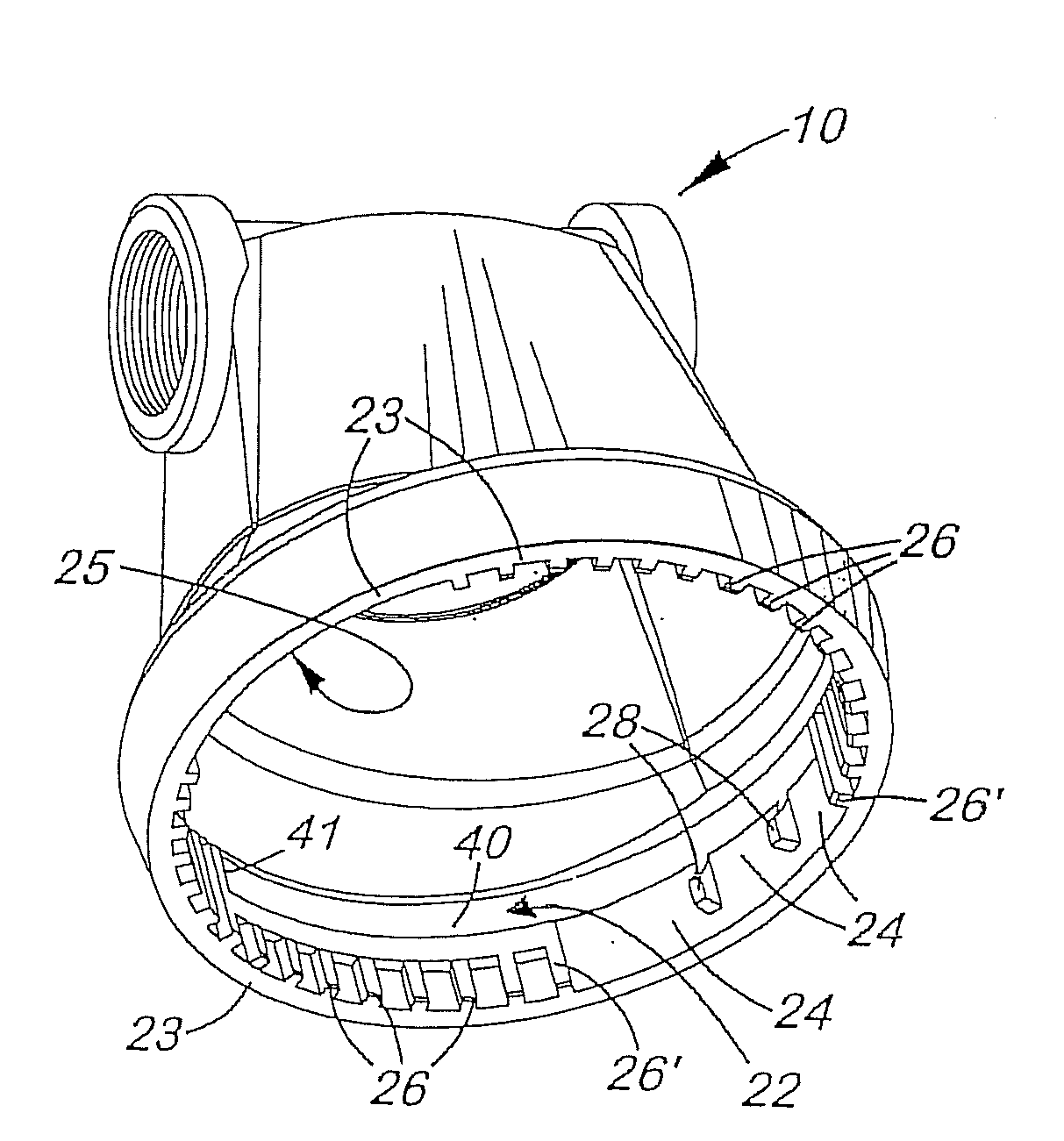
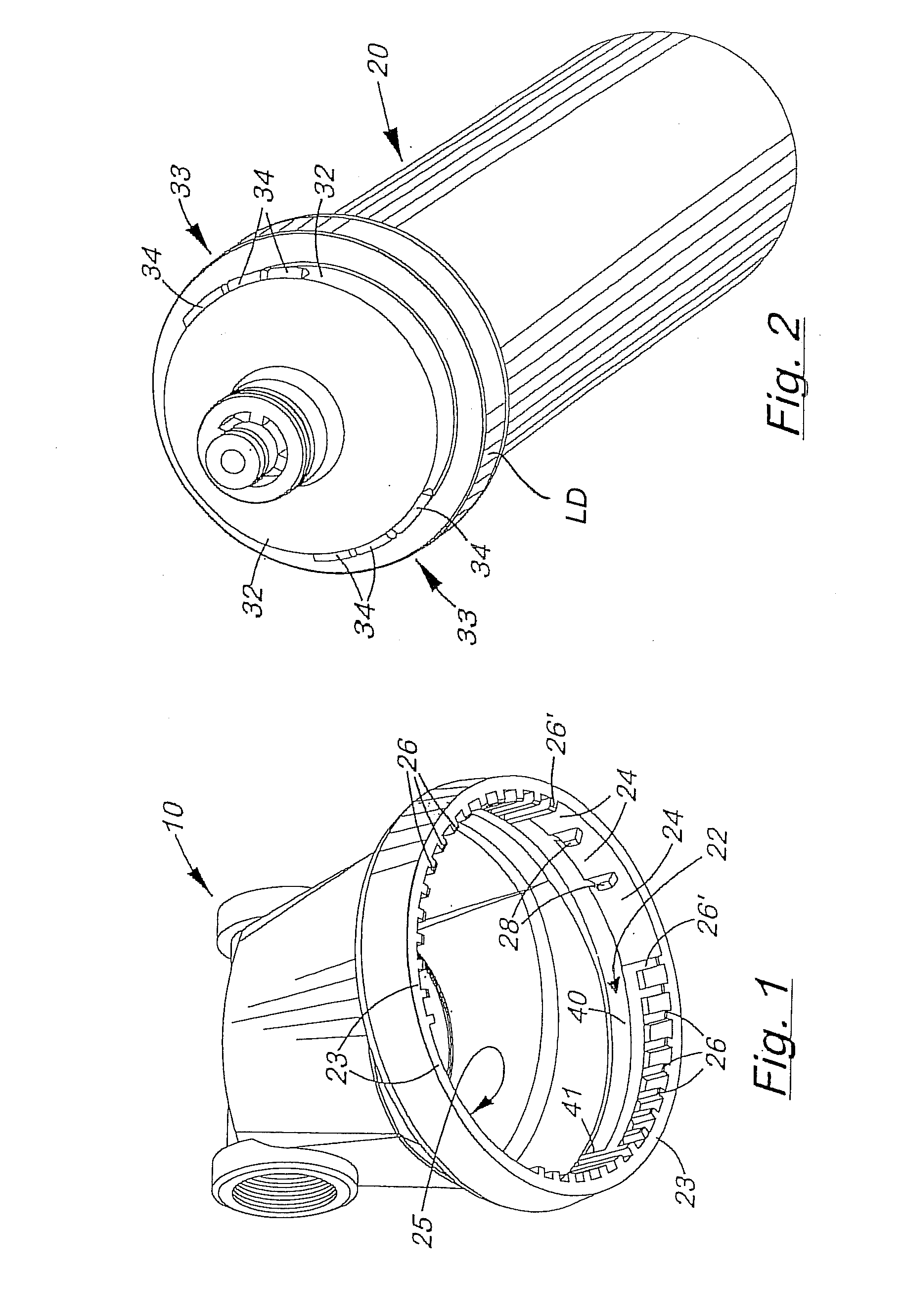
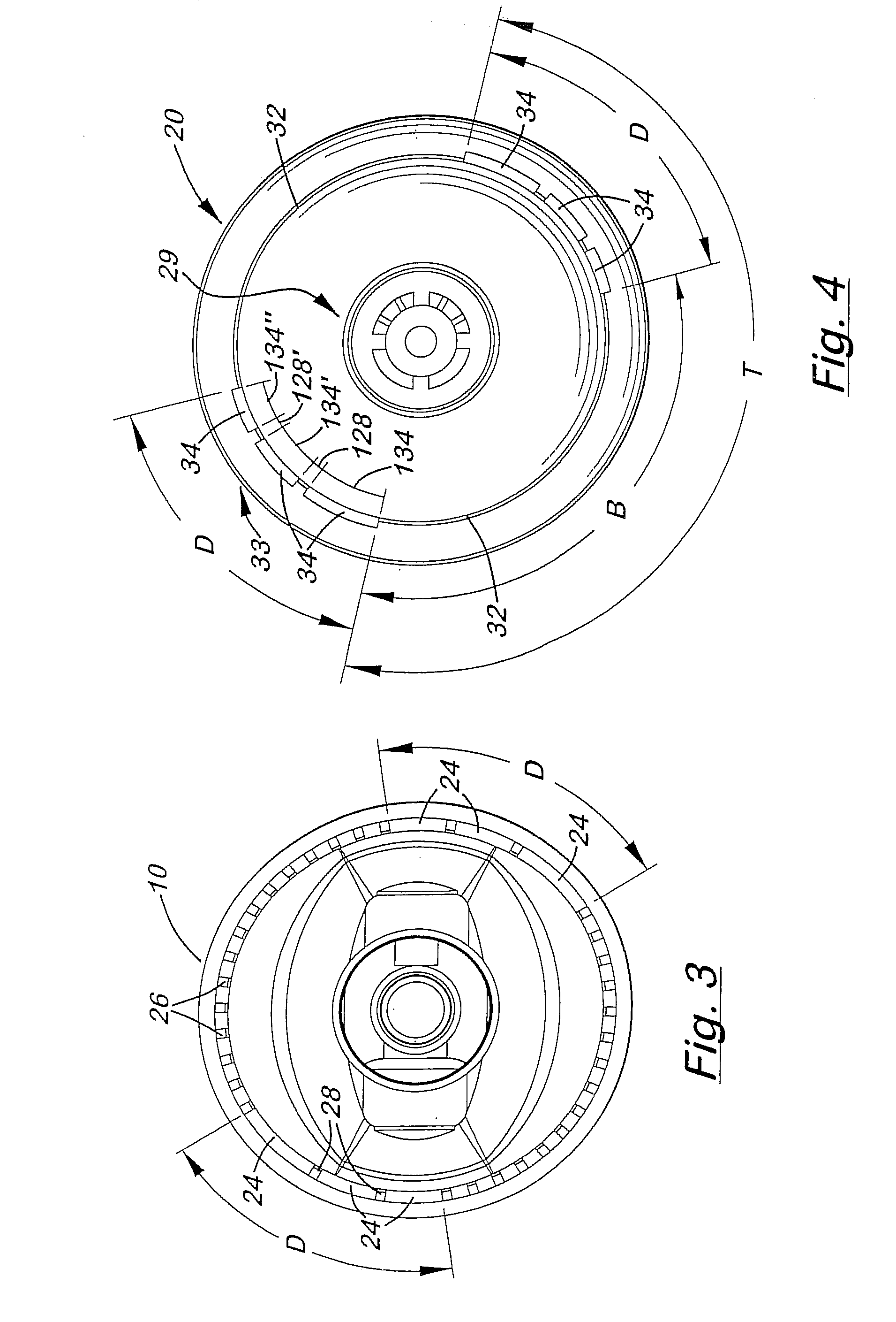
[0037]Referring to the Figures, there are shown several, but not the only embodiments of the invented key system. FIGS. 1-11 illustrate a keyed filter embodiment of the invented keyed system, wherein the embodiment may be called a “keyed shoulder” embodiment because the protrusion structure is on a shoulder at a location slightly above the largest-diameter portion of the housing, wherein the shoulder has a diameter between said largest-diameter portion and the neck of the filter. FIGS. 12-44 illustrates alternative embodiments of filters and cooperating filter heads, wherein the keyed structure is also located between the largest-diameter portion of the filter top end and the neck of the filter, and comprises keyed plates / flange(s) connected to the upper radial surface of the filter housing and extending out generally parallel to said upper radial surface away from two sides of the base of the central neck.

[0038]The key system structures are located on surfaces of filters and holder...


PUM

PropertyMeasurementUnit
Fractionaaaaaaaaaa
Fractionaaaaaaaaaa
Angleaaaaaaaaaa

Abstract

A filter and its holder each have a keyed surface, one being a protruding “key” and one being a recessed “lock,” wherein cooperation of these keyed surfaces is required in order for the filter to be installed in the holder. Modification/adaptation of the keyed surfaces, by changing the location, number and length of the key protrusions and cooperating recesses during manufacture, allows various sets of mating filters and holders to be produced so that only mating/matching filters and holders may be connected together. The keyed protrusions are preferably located on an upper shoulder or on protruding flange(s) of the upper end of the filter. The cooperating recess structure inside the filter holder comprises axial recesses that allow axial insertion of the key protrusions, and hence the filter, into the holder and also a circumferential recesses portion that receives multiple key protrusions to retain the filter in the holder. This way, multiple key protrusions slide into and are retained in a single circumferential recess/slot, rather than each key protrusion being received in its own separate circumferential recess/slot.

Description

[0001]This application claims benefit of Provisional Application Ser. No. 61 / 235,693, filed Aug. 21, 2009, and also of Provisional Application Ser. No. 61 / 310,204, filed Mar. 3, 2010, the entire disclosures of which are incorporated herein by this reference.BACKGROUND OF THE INVENTIONField of the Invention[0002]This invention relates generally to fluid filters and filters and connections for the filters / cartridges to piping, valving, brackets, and other holders that cooperate with the filters / cartridges to make them operative in a flowing fluid system. More specifically, this invention relates to a system for “keying” a particular filter or filter cartridge to a particular cooperating filter head member or filter valve head.SUMMARY OF THE INVENTION[0003]The invention is an apparatus and method wherein a portion of a fluid filter-holder connection is structurally adapted so that only matched filters and holders can cooperate to allow installation of the filter in the holder and / or to...

Claims


Application Information

Patent Timeline
IPC IPC(8): B01D35/30
CPCB01D35/301B01D2201/302C02F2201/006C02F2201/004B01D2201/4046
Inventor REID, ROGER P.
Owner OMNIPURE FILTER CO INC
Why Eureka
Try Eureka