Door and window structure

A technology for doors and windows and window frames, applied in the field of doors and windows, can solve the problems of easy accumulation of dust and inconvenient cleaning of dust.

Inactive Publication Date: 2021-04-02
王宁可
View PDF0 Cites 1 Cited by
  • Summary
  • Abstract
  • Description
  • Claims
  • Application Information

AI Technical Summary

Problems solved by technology

[0003] There are many high-rise buildings in modern buildings. The windows can not only achieve good lighting effect, but also facilitate the indoor ventilation of the building. At the same time, the windows can increase the aesthetics of the building. , forming a compartment, dust is easy to accumulate in the compartment, and it is very inconvenient to clean the dust in the compartment. Therefore, a corresponding improvement is made to solve this problem, and a door and window structure that is easy to clean is proposed

Method used


Image

  • Door and window structure
  • Door and window structure
  • Door and window structure

Examples


Embodiment 1

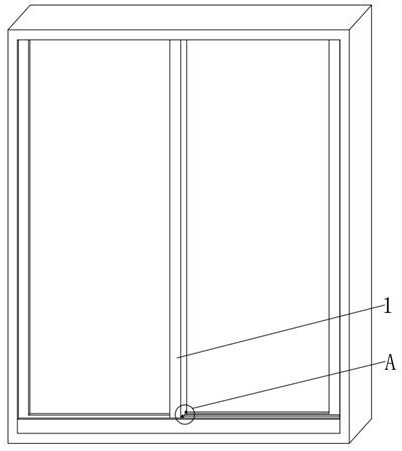
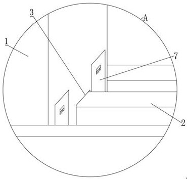
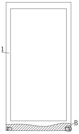
[0036] refer to Figure 1-8, a door and window structure, including two window frames 1 installed in the window frame, a tempered glass plate is bonded inside the window frame 1, a coaming plate and two guide plates 2 are fixed on the top and bottom of the inner wall of the window frame by bolts, The hoarding is arranged at the front end of the window frame 1, and the top and bottom of the window frame 1 are provided with guide grooves 3, the guide groove 3 is nested and connected with the corresponding guide plate 2, and two first grooves are provided on both sides of the bottom of the window frame 1 4 and the second groove 6, the inner wall of the first groove 4 is connected with the pulley 5 through bearing rotation, and the outer wall of the pulley 5 is provided with a plurality of ring grooves distributed evenly in the longitudinal direction, and a rubber ring is set in the ring groove, and the second groove 6. There is an ash collection box 7 built in. A dust guide plate...

Embodiment 2

[0047] refer to Figure 1-9 , a door and window structure, the dust guide plate 8 is arranged to be connected to the inner wall of the first groove 4 through bearing rotation, and the same third spring is fixed between the bottom of the dust guide plate 8 and the side wall of the first groove 4 by bolts 29.

[0048] During use, when the pulley 5 rotates, the force between the pulley 5 and the ash pushing plate 8 is transmitted to the ash guiding plate 8, and under the action of the third spring 29, the ash guiding plate 8 rotates back and forth at a certain angle, Thereby, the dust on the ash guide plate 8 is turned to the side close to the ash collection box 7, so that more dust is completely entered into the ash collection box 7 for collection, thereby further improving the dust cleaning effect.


PUM


Abstract

The invention belongs to the technical field of doors and windows, particularly relates to a door and window structure, and provides the following scheme for solving the problem that an existing doorand window structure is inconvenient in dust removal. The door and window structure comprises two window frames, coamings and two guide plates are fixed at the top and the bottom of the inner wall ofa window sash, and guide grooves are formed in the top and the bottom of each window frame; and two first grooves and second grooves are formed in the two sides of the bottom of each window frame correspondingly, pulleys are rotatably connected to the inner walls of the first grooves, dust guide plates are fixed in the first grooves, baffles are welded to the two ends of the tops of the dust guideplates, connecting plates are arranged on the inner sides of the dust guide plates, dust pushing plates are fixed to the inner sides of the connecting plates, arc-shaped parts are arranged at the bottoms of the dust pushing plates, and the dust pushing plates make natural contact with the tops of the pulleys. According to the door and window structure, when a window is opened or closed, the pulleys rotate, the dust in separation grooves is adhered to the surfaces of the pulleys, the dust pushing plates scrape the dust on the surfaces of the pulleys, and the dust enters a dust collection box along the dust guide plates to be collected under the inertia effect, so that the effect of convenient cleaning is achieved.

Description

technical field [0001] The invention relates to the technical field of doors and windows, in particular to a door and window structure. Background technique [0002] Doors and windows are divided into enclosure components or partition components according to their positions, which are important components in the building enclosure structure system. According to different design requirements, it has functions such as heat preservation, heat insulation, sound insulation, waterproof, and fire prevention; the window of modern windows is composed of three parts: window frame, glass and movable components. The window frame is responsible for supporting the main structure of the window, the glass is attached to the window frame, and the movable components are mainly hinges, handles, pulleys, etc. [0003] There are many high-rise buildings in modern buildings. The windows can not only achieve good lighting effect, but also facilitate the indoor ventilation of the building. At the ...

Claims


Application Information

Patent Timeline
Patent Type & Authority Applications(China)
IPC IPC(8): E06B7/28E05D13/00A47L1/00
CPCA47L1/00E05D13/00E06B7/28
Inventor 王宁可
Owner 王宁可
Why Eureka
Try Eureka