
Work monitoring system for machine tool

A monitoring system and work technology, applied in the direction of test/monitoring control system, general control system, control/regulation system, etc., can solve problems without specific explanation

Active Publication Date: 2021-04-02
MATSUURA MACHINERY
View PDF12 Cites 0 Cited by
  • Summary
  • Abstract
  • Description
  • Claims
  • Application Information

AI Technical Summary

Problems solved by technology

[0013] However, in Patent Document 2, there is no specific description of how the system strictly distinguishes abnormal operations among the plurality of components of the operating machinery.
[0014] According to the applicant's search, there has not been found a basis for a mechanism that can monitor the abnormality of each machine tool installed in the workplace without strictly distinguishing the signals for notifying abnormality among multiple machine tools. Known technology such as identifying the abnormal machine tool on the

Method used


Image

  • Work monitoring system for machine tool
  • Work monitoring system for machine tool

Examples


Embodiment 1

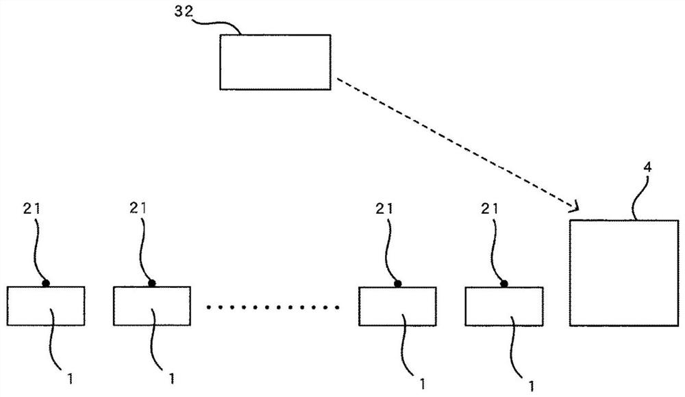
[0062] Embodiment 1 is based on the basic configuration (2), and is characterized in that, in each lamp 21, the color corresponding to the case within the normal operating range, the color corresponding to the case exceeding the normal operating range, and the color corresponding to the case of exceeding the normal operating range are respectively lit. And the color of the situation where the work is completed, at the place where the work monitoring of each machine tool 1 is carried out, specifically at the monitoring site 4, the change state of the color of each machine tool 1 is recorded, and the frequency of abnormal occurrence in each machine tool 1 is recorded. degree for statistics.

[0063] By counting the occurrence frequency of abnormalities in each machine tool 1 as described above, it is possible to statistically analyze problems and defects in the operation of each machine tool 1 .

Embodiment 2

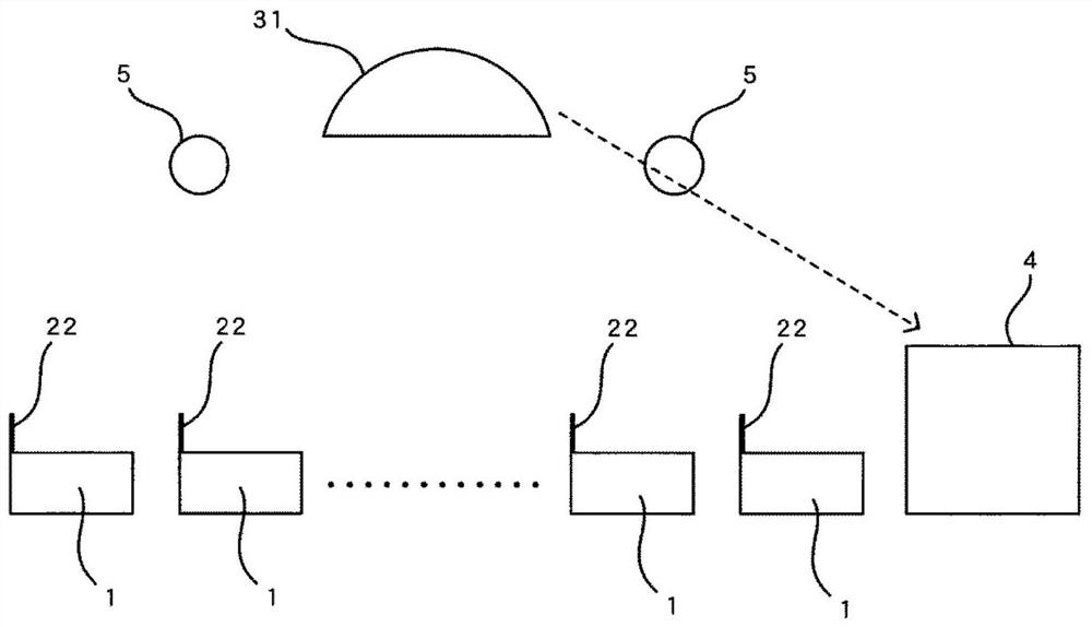
[0065] Embodiment 2 is based on the basic structure (1), and is characterized in that, in each reflective display panel 22, the position corresponding to the situation of normal operation and the position corresponding to the situation of exceeding the normal operation range are respectively set. position, and the position of the situation where the work is completed, and at the place where the work monitoring of each machine tool 1 is carried out, specifically at the monitoring site 4, the change state of the position of each reflector is recorded, and the abnormality in each machine tool 1 The frequency of occurrence is counted.

[0066] Also in the second embodiment, similarly to the first embodiment, problems and defects in the operation of each machine tool 1 can be statistically analyzed.


PUM


Abstract

Provided is a configuration of a machine tool operation monitoring system that specifies a machine tool in which an operation abnormality has occurred without requiring a special strict discriminationmark. A machine tool operation monitoring system detects abnormal operation of a machine tool (1), and detects abnormal operation of the machine tool (1) if the abnormal operation exceeds the range of normal operation of a drive motor of each machine tool (1) and / or if the movement conditions of constituent parts and materials of the machine tool (1) exceed the normal range. The problem is solvedby determining a machine tool (1) in which an operation abnormality has occurred on the basis of either a monitoring of an image projected onto a camera (31) by reflected light from a reflective display panel (22) provided to each machine tool (1) or b monitoring of a difference in the projection direction of light emitted from a lamp (21) provided to each machine tool (1) onto a light sensor (32).

Description

technical field [0001] The present invention is directed to an operation monitoring system of a machine tool for monitoring whether or not a plurality of machine tools arranged in a workplace are operating normally. Background technique [0002] When a predetermined object is automatically processed based on automatic control by a plurality of processing devices arranged in a workplace, a monitoring system for judging whether the operation status of each processing device is normal or not is essential. [0003] The necessity of the above-mentioned determination is particularly obvious when the processing device is a machine tool. In the prior art, when the operation of the machine is detected, a detection signal notifying an abnormality sent by an individual processing device in operation is wirelessly transmitted. Or wired to the monitoring device. [0004] However, in the case of transmitting such a signal, a mechanism for strictly distinguishing from which processing dev...

Claims


Application Information

Patent Timeline
Patent Type & Authority Applications(China)
IPC IPC(8): B23Q17/00B23Q11/00B23Q11/12G08B25/00G05B19/418
CPCY02P90/02G05B19/4184G05B2219/37234G05B19/4065G05B2219/37571B23Q11/0089B23Q11/0085B23Q17/0952B23Q17/10G05B23/0237G05B23/0256B23Q11/10G05B2219/34465
Inventor 天谷浩一武泽泰则山内和也
Owner MATSUURA MACHINERY
Learn More