
A three-phase switched reluctance motor integrated boost power converter and its control method

A technology of power converter and reluctance motor, which is applied in the direction of motor generator control, AC motor control, DC power input conversion to DC power output, etc., which can solve the problems of high demand for driving resources and increase of power devices, and achieve reduction Effects of using and saving drive resources

Active Publication Date: 2021-11-16
NANJING UNIV OF INFORMATION SCI & TECH
View PDF6 Cites 0 Cited by
  • Summary
  • Abstract
  • Description
  • Claims
  • Application Information

AI Technical Summary

Problems solved by technology

[0003] The typical power topology of switched reluctance motor is an asymmetrical half-bridge. Each bridge arm needs two freewheeling diodes and two switching tubes. If it is necessary to boost the bus voltage, it needs to The cascaded DC-DC converter constitutes a two-stage structure. This solution adds two additional switching tubes, and the number of power devices is increased. At the same time, the front, rear and control are separated from each other, and the demand for driving resources is large.

Method used


Image

  • A three-phase switched reluctance motor integrated boost power converter and its control method
  • A three-phase switched reluctance motor integrated boost power converter and its control method
  • A three-phase switched reluctance motor integrated boost power converter and its control method

Examples


Embodiment Construction

[0044] The specific implementation manners of the present invention will be further described in detail below in conjunction with the accompanying drawings.

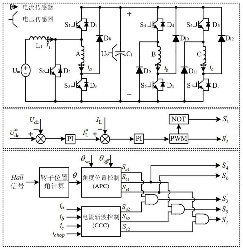
[0045] The present invention designs a three-phase switched reluctance motor integrated boost power converter, such as figure 1 shown, including the DC power supply U in , the first IGBT transistor S 1 , the first freewheeling diode D 1 , the second IGBT transistor S 2 , the second freewheeling diode D 2 , the third IGBT transistor S 3 , the third freewheeling diode D 3 , the fourth IGBT transistor S 4 , the fourth freewheeling diode D 4 , the fifth IGBT transistor S 5 , the fifth freewheeling diode D 5 , the sixth IGBT transistor S 6 , the sixth freewheeling diode D 6 , the seventh IGBT transistor S 7 , the seventh freewheeling diode D 7 , the eighth freewheeling diode D 8 , the ninth freewheeling diode D 9 , the tenth freewheeling diode D 10 , the eleventh freewheeling diode D 11 , the twelfth freewhee...


PUM


Abstract

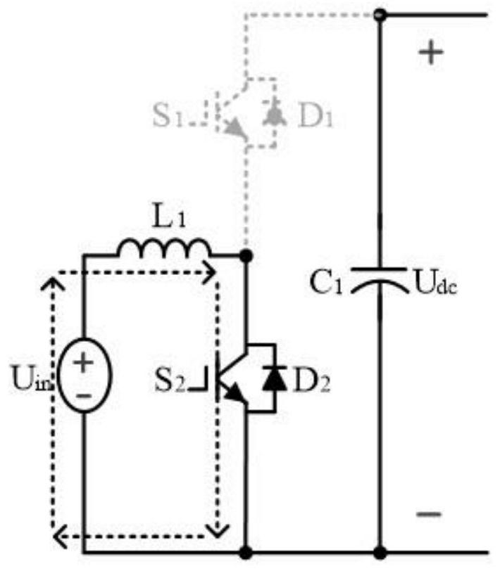
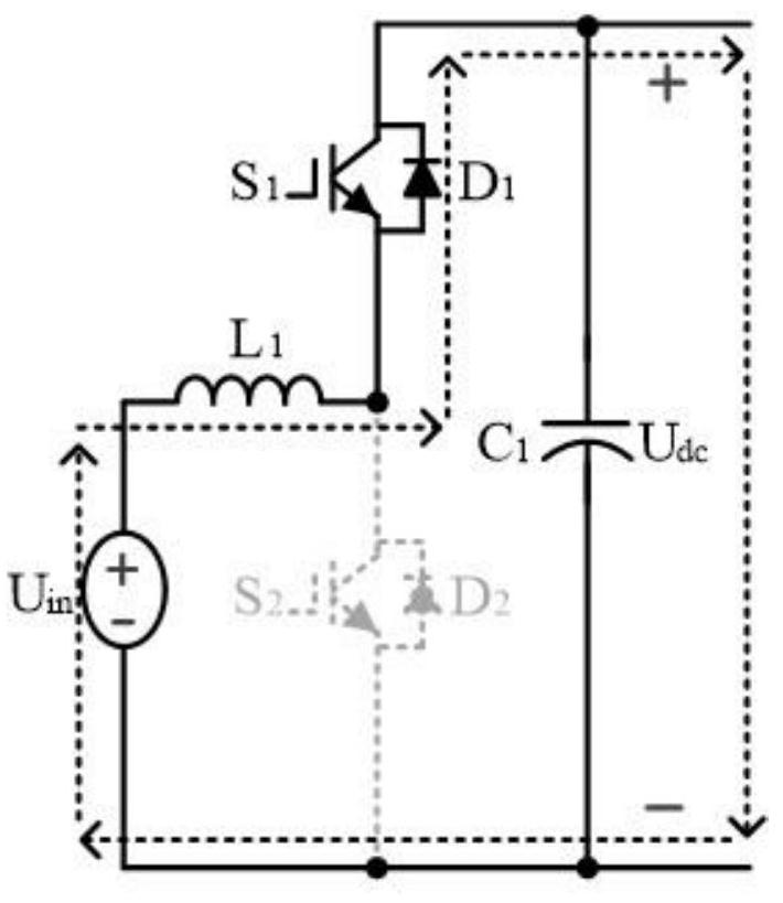
The invention relates to a three-phase switched reluctance motor integrated boost power converter and a control method, which are aimed at the lower freewheeling diodes of the middle and A-phase bridge arms of the three-phase asymmetrical half bridge of the three-phase switched reluctance motor. The second IGBT transistor S 2 Instead, connect the DC power supply and the inductance series branch in parallel at both ends of the switch tube, so that the first IGBT transistor S on the A-phase bridge arm 1 with the third IGBT transistor S 3 A step-up DC-DC converter power circuit is formed, so that the new A-phase bridge arm realizes the integration of the step-up DC-DC converter and the asymmetrical half-bridge arm without adding power devices. The whole scheme uses The switched reluctance motor power converter can realize the integration of topology and control in the one-phase bridge arm of the three-phase asymmetrical half-bridge power circuit by the step-up DC-DC converter without adding switching devices, so that the other two The excitation and demagnetization voltages of the phase windings have the ability to boost and adjust.

Description

technical field [0001] The invention relates to a three-phase switched reluctance motor integrated boost power converter and a control method, belonging to the technical field of motor drive control. Background technique [0002] The switched reluctance motor is a doubly salient pole structure, which has the characteristics of large starting torque, convenient control, low cost, good fault tolerance and high efficiency. It is beneficial to the miniaturization and integration of the switched reluctance motor system. [0003] The typical power topology of switched reluctance motor is an asymmetrical half-bridge. Each bridge arm needs two freewheeling diodes and two switching tubes. If it is necessary to boost the bus voltage, it needs to The cascaded DC-DC converter constitutes a two-stage structure. This solution adds two additional switching tubes, and the number of power devices is increased. At the same time, the front, rear and control are separated from each other, and ...

Claims


Application Information

Patent Timeline
Patent Type & Authority Patents(China)
IPC IPC(8): H02M3/158H02P25/092
CPCH02M3/158H02P2201/09H02P25/092
Inventor 蔡骏董逸茹束寅志严颖赵兴强
Owner NANJING UNIV OF INFORMATION SCI & TECH
Learn More