Medical lumbar traction bed

A technology of lumbar traction and bed master, applied in the field of medical equipment, can solve problems such as not being able to reduce pain

Inactive Publication Date: 2021-04-09
何岩
View PDF1 Cites 1 Cited by
  • Summary
  • Abstract
  • Description
  • Claims
  • Application Information

AI Technical Summary

Problems solved by technology

[0002] For example, the public CN201642461U includes a bed frame and a bed leg. A threaded screw is arranged under the bed frame. Both ends of the threaded screw are arranged on the bed frame through bearing seats. Nuts are arranged on the threaded screw. It is connected with a supporting frame, the top of the supporting frame is provided with a mobile traction frame, the lower part of the supporting frame is provided with a pulley, a slide rail is provided between the legs of the bed, the pulley is located on the slide rail, one end of the screw is provided with a rocker, and the Fixed with a fixed traction frame; the disadvantage of this invention is that it does not reduce the pain caused by body stretching

Method used


Image

  • Medical lumbar traction bed
  • Medical lumbar traction bed
  • Medical lumbar traction bed

Examples


specific Embodiment approach 1

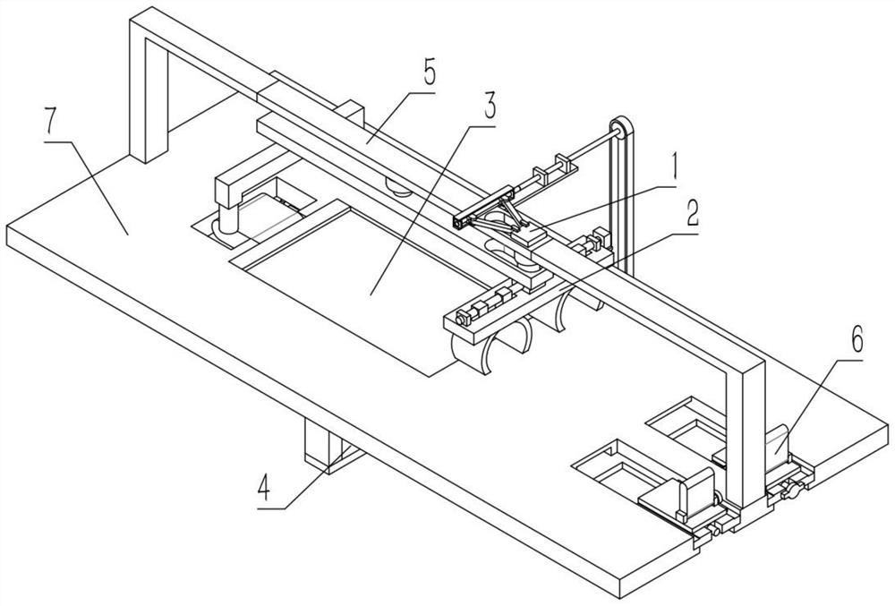
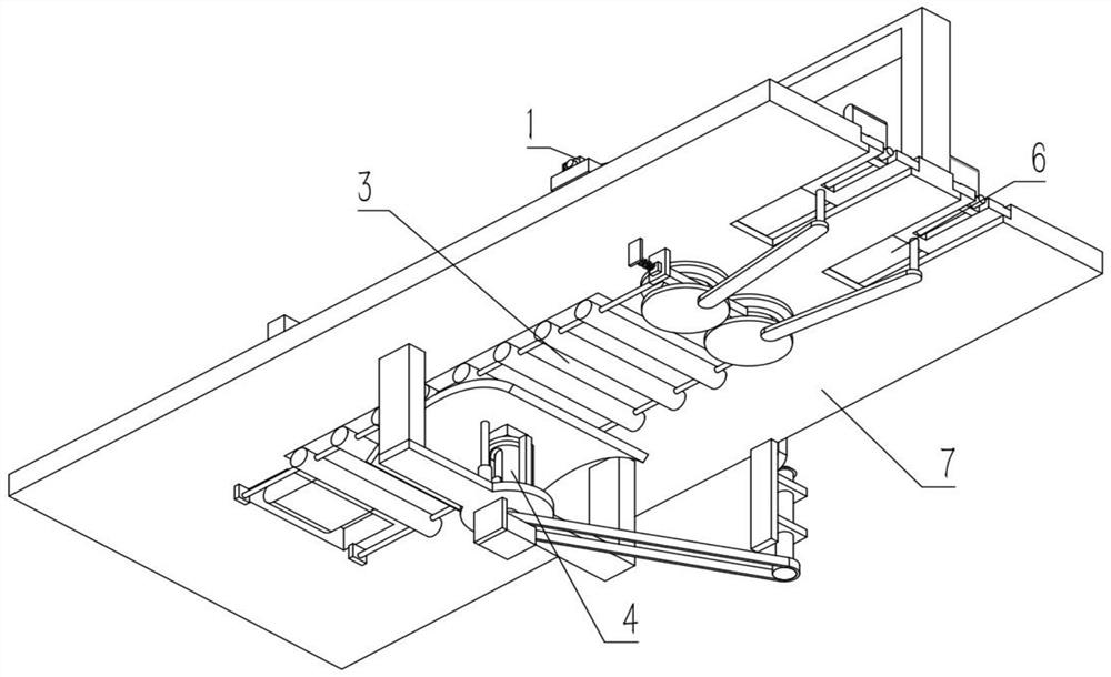
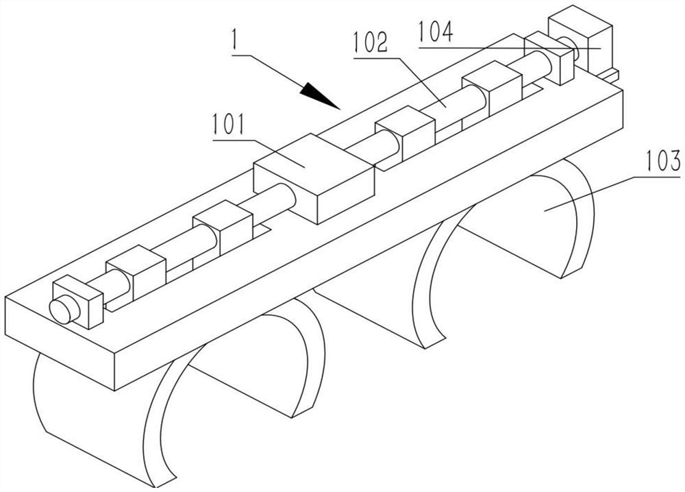
[0030] Combine below Figure 1-9 Describe this embodiment, a medical lumbar traction bed, including a clamping mechanism 1 and a support mechanism 2, the clamping mechanism 1 includes a clamping frame 101, a screw rod 102, a leg clamping plate 103 and a clamping motor 104, The screw mandrel 102 is rotatably connected to the clamping frame 101, the screw mandrel 102 and a plurality of leg clamping plates 103 are threaded, the screw mandrel 102 is fixedly connected to the output shaft of the clamping motor 104, and the plurality of leg clamping plates 103 All are slidingly connected on the clamping frame 101, and the clamping motor 104 is fixedly connected on the clamping frame 101. The support mechanism 2 includes a supporting roller 201, a connecting line 202 and a sponge pad 206, and a plurality of supporting rollers 201 are fixedly connected on two On the connection line 202, the sponge pad 206 is fixedly connected to a plurality of supporting rollers 201;

[0031] Under no...

specific Embodiment approach 2

[0033] Combine below Figure 1-9Describe this embodiment, this embodiment will further explain the first embodiment, the support mechanism 2 also includes a gear 203, a rack 204 and a bobbin 205, the two gears 203 are meshed for transmission, and the rack 204 is meshed with the bobbin 205 at the right end Transmission, the two bobbins 205 are respectively fixedly connected to the two gears 203, and the two connecting wires 202 are respectively fixedly connected to the two bobbins 205;

[0034] A part of the right ends of the two connecting wires 202 grow out, and are respectively wound on the two bobbins 205. The upward movement of the middle parts of the plurality of support rollers 201 will stretch the two connecting wires 202, and the right ends of the two connecting wires 202 are stretched to drive two The winding shaft 205 rotates, and the two winding shafts 205 rotate to drive the two gears 203 to rotate. The winding shaft 205 at the right end drives the rack 204 to move...

specific Embodiment approach 3

[0036] Combine below Figure 1-9 Describe this embodiment mode, this embodiment mode will further illustrate embodiment 2, described a kind of medical lumbar traction bed also comprises transmission mechanism 3, transmission mechanism 3 comprises telescoping rod 301, sliding block 302, rotating rod 303, moving block 304, The transmission frame 305 and the transmission screw mandrel 306, the telescopic rod 301 are fixedly connected on the sliding block 302, the two rotating rods 303 are all rotatingly connected on the sliding block 302, and the two rotating rods 303 are respectively rotatingly connected on the two moving blocks 304, The two moving blocks 304 are threaded with the transmission screw 306, the two moving blocks 304 are slidingly connected to the transmission frame 305, the transmission screw 306 is rotatably connected in the transmission frame 305, and the clamping frame 101 is fixedly connected to the telescopic rod 301 superior;

[0037] The rotation of the tra...


PUM


Abstract

The invention relates to the technical field of medical instruments, in particular to a medical lumbar traction bed. The bed comprises a clamping mechanism and a supporting mechanism, wherein the clamping mechanism comprises a clamping frame, a lead screw, leg clamping plates and a clamping motor; the lead screw is rotationally connected to the clamping frame; the lead screw and the multiple leg clamping plates are in threaded transmission; the lead screw is fixedly connected to an output shaft of the clamping motor; the multiple leg clamping plates are all connected to the clamping frame in a sliding mode; the clamping motor is fixedly connected to the clamping frame; the supporting mechanism comprises supporting rollers, connecting lines and sponge mats; the multiple supporting rollers are all fixedly connected to the two connecting lines; and the sponge mats are fixedly connected to the supporting rollers. The pain caused by body stretching can be reduced, the lumbar traction effect can be guaranteed, and a patient can have better treatment experience.

Description

technical field [0001] The invention relates to the technical field of medical devices, in particular to a medical lumbar traction bed. Background technique [0002] For example, the public CN201642461U includes a bed frame and a bed leg. A threaded screw is arranged under the bed frame. Both ends of the threaded screw are arranged on the bed frame through bearing seats. Nuts are arranged on the threaded screw. It is connected with a supporting frame, the top of the supporting frame is provided with a mobile traction frame, the lower part of the supporting frame is provided with a pulley, a slide rail is provided between the legs of the bed, the pulley is located on the slide rail, one end of the screw is provided with a rocker, and the Fixed with a fixed traction frame; the shortcoming of this invention is that it cannot reduce the pain produced by body stretching. Contents of the invention [0003] The purpose of the present invention is to provide a medical lumbar trac...

Claims


Application Information

Patent Timeline
Patent Type & Authority Applications(China)
IPC IPC(8): A61F5/042A61F5/045
CPCA61F5/042A61G13/1205
Inventor 何岩
Owner 何岩
Why Eureka
Try Eureka