A flexible manipulator system and continuum robot for deep cavity operation

A technology for flexible manipulators and deep cavity operations. It is applied in the direction of manipulators, program-controlled manipulators, and manufacturing tools. It can solve the problems of difficult design layout, small number of degrees of freedom, and large structural size to meet monitoring and maintenance tasks. The effect of many controllable degrees of freedom and compact structure

Active Publication Date: 2022-04-01
XIDIAN UNIV
View PDF8 Cites 0 Cited by
  • Summary
  • Abstract
  • Description
  • Claims
  • Application Information

AI Technical Summary

Problems solved by technology

Among them, the structural size of their mechanical bodies and control parts is relatively large. The most important reason is that due to the limitation of degrees of freedom and controllability, the length of the flexible arm of the ultra-redundant robot cannot meet the inspection and maintenance tasks of large equipment.
Taking the Haian Jiaorui robot as an example, the length of the executive body is only 1235mm, which cannot solve the overhaul and maintenance tasks of super-large equipment
[0003] Through the above analysis, the existing problems and defects of the existing technology are as follows: the existing ultra-redundant robot has a large structure size and relatively few degrees of freedom, and the friction force of the flexible cable or rod is relatively large during the movement process. The problem of disc torsion resistance is more complicated, and the mechanical part and the control part of the electric cabinet cannot be integrated into one design or the design together is quite large in size
[0004] The difficulty of solving the above problems and defects is: to ensure the installation of more drive units under the small structure size, to ensure the selection, layout and wiring of each module under the small structure size; the design layout is more difficult

Method used


Image

  • A flexible manipulator system and continuum robot for deep cavity operation
  • A flexible manipulator system and continuum robot for deep cavity operation
  • A flexible manipulator system and continuum robot for deep cavity operation

Examples


Embodiment Construction

[0051] In order to make the object, technical solution and advantages of the present invention more clear, the present invention will be further described in detail below in conjunction with the examples. It should be understood that the specific embodiments described here are only used to explain the present invention, not to limit the present invention.

[0052] Aiming at the problems existing in the prior art, the present invention provides a flexible manipulator system for deep cavity operation. The present invention will be described in detail below with reference to the accompanying drawings.

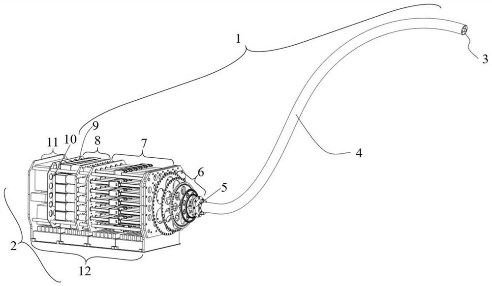
[0053] Such as figure 1 As shown, the flexible manipulator system for deep cavity operation provided by the embodiment of the present invention includes a functional end 1 and a control end 2;

[0054] Functional end 1 includes:

[0055] The flexible manipulator module 4 uses a set of criss-cross nickel-titanium alloy plates as the structural main frame, in which the number of s...


PUM


Abstract

The invention belongs to the technical field of special robots, and discloses a flexible manipulator system and a continuum robot for deep cavity operations, including a functional end and a control end; the functional end includes: a flexible manipulator module, a camera and lighting module, a top fixing module, Scaling module, drive module, transmission module, sensor module; the control terminal includes: flexible manipulator control module, camera and lighting control module, which moves the flexible manipulator to the specified pose; sensor control module, realizes the position feedback of the drive device and the flexible Acquisition and feedback of cable or rod tension pressure realizes real-time force acquisition and initial pretension function of the force sensor during the rope driving process. The invention has strong versatility, high degree of modularization, safety and relatively small size; at the same time, it reduces the friction between the steel-plastic hose and the shrink disc; The large sliding friction force and the fixing method of the spacer discs enable the continuum robot to have sufficient torsional rigidity.

Description

technical field [0001] The invention belongs to the technical field of special robots, and in particular relates to a flexible manipulator system and a continuum robot for deep cavity operations. Background technique [0002] At present, performing fine tasks in a narrow and congested environment has always been a bottleneck that traditional continuum robots are difficult to overcome. Hyper-redundant snake robots or infinitely redundant continuum robots offer possibilities for robots to perform tasks in confined spaces. Due to the high cost of inspection and maintenance of large equipment. Therefore, hyper-redundant robots have attracted the attention of many researchers in recent years. Earlier OC robots were mainly used for inspection and maintenance of nuclear reaction equipment, and the robot has 20 degrees of freedom. Both Shenyang Institute of Automation and Haian Jiaorui Robotics have developed super-redundant robots with 24 degrees of freedom and 25 degrees of fre...

Claims


Application Information

Patent Timeline
Patent Type & Authority Patents(China)
IPC IPC(8): B25J9/10B25J13/08B25J19/02
CPCB25J9/104B25J13/085B25J19/023
Inventor 王红红杜敬利沈南阳李雨亨吴天瑜
Owner XIDIAN UNIV
Why Eureka
Try Eureka