Automatic unfolding sliding type parabolic antenna

A parabolic antenna, self-expanding technology, applied to antennas, folded antennas, electrical components and other directions, can solve the problems that the antenna cannot work quickly and delay, and achieve the effect of ensuring repeated positioning, low cost and simple maintenance.

Pending Publication Date: 2018-09-11
NO 54 INST OF CHINA ELECTRONICS SCI & TECH GRP
View PDF0 Cites 0 Cited by
  • Summary
  • Abstract
  • Description
  • Claims
  • Application Information

AI Technical Summary

Problems solved by technology

[0003] The technical problem to be solved by the present invention is to provide an automatic unfolding sliding parabolic antenna that can be quickly and automatically assembled and stored in order to overcome the serious delay defect caused by manual assembly of the antenna when the antenna enters the working area and cannot work quickly and quickly transfer

Method used


Image

  • Automatic unfolding sliding type parabolic antenna
  • Automatic unfolding sliding type parabolic antenna
  • Automatic unfolding sliding type parabolic antenna

Examples


Embodiment 1

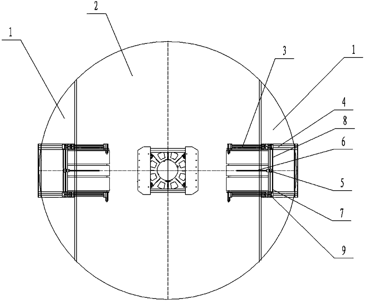
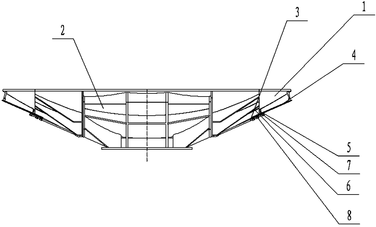
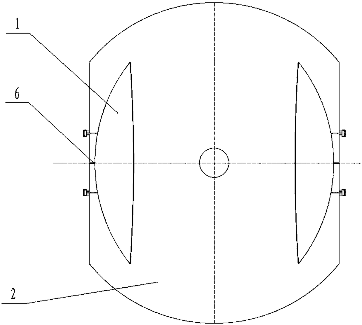
[0025] In Example 1, there are two linear slide bars, a beam 8 is fixed at the corresponding position between the two linear slide bars, the lower end of the telescopic device is mounted on the inner beam 7, the top of the expansion device is connected to the back of the sliding surface. match. A slit 6 for the telescopic device to pass through is opened on the fixed surface, and the direction of the slit is consistent with the direction of the linear sliding rod.

Embodiment 2

[0026] In Embodiment 2, the number of the linear sliding rods is one or two, and the linear sliding rod is equipped with an outer beam, the beam extends to the outside of the outer edge of the parabolic antenna, and the lower end of the telescopic device is installed on the outer beam; An outer crossbar extending to the outside of the outer edge of the parabolic antenna is installed on the back of the telescopic antenna, and the top end of the telescopic device is matched with the outer crossbar.

Embodiment 3

[0027] In Embodiment 3, the sliding surface may be a reflective surface unit located at any position on the edge of the antenna.


PUM


Abstract

The invention relates to an automatic unfolding sliding type parabolic antenna. The antenna comprises a plurality of reflecting surface units; a certain reflecting surface unit located at the edge ofthe parabolic antenna is a sliding surface; a fixed surface is in butt joint with the sliding surface; the back of the fixed surface is provided with linear slide rails and linear slide bars matched with the linear slide rails; the linear slide bars are equipped with a telescopic device; the bottom end of the telescopic device is fixed on the linear slide bars; the top end of the telescopic deviceand the back of the sliding surface are assembled in a matched manner; the telescopic direction of the telescopic device is consistent with the normal direction of the parabolic antenna; and the sliding direction of the linear slide bars is consistent with the tangential direction of the parabolic antenna. When the automatic unfolding sliding type parabolic antenna is to be folded, the telescopicdevice begins to elongate, so that the lowest position of the sliding surface is higher than the fixed surface; the linear sliding bars contract from the linear sliding rails to the center of the antenna; the sliding surface is made to move to a position above the fixed surface; and therefore, the folding of the antenna can be realized. When the antenna is to be unfolded, the above operation is reversed, so that the antenna can be unfolded. The antenna can be automatically unfolded and folded.

Description

technical field [0001] The invention relates to an antenna for satellite communication, electronic interference, and navigation measurement and control equipment, and belongs to the technical field of communication equipment. Background technique [0002] In the era of communication globalization, satellite communication occupies an irreplaceable and important position in the field of communication due to its wide coverage, large communication capacity and high communication efficiency. With the rapid development of communication, measurement and control technology, the requirements for antennas are getting higher and higher. At present, the communication antennas that respond quickly and work, especially the mobile station requirements, if the antenna cannot move quickly, it is convenient for transportation and use, and the accuracy is guaranteed. , and it will be impossible to talk about in the following communication. At present, the large antennas on the market are main...

Claims


Application Information

Patent Timeline
Patent Type & Authority Applications(China)
IPC IPC(8): H01Q15/16H01Q1/08
CPCH01Q15/16H01Q1/08
Inventor 李增科张晓冲何翠瑜李吉康
Owner NO 54 INST OF CHINA ELECTRONICS SCI & TECH GRP
Why Eureka
Try Eureka