Buffering material receiving device for coal mine
A material receiving device and coal mine technology, which is applied in the direction of transportation and packaging, conveyors, conveyor objects, etc., can solve the problems of short service life, large moving friction between the material receiving plate and the cylinder, and wear, so as to improve the service life, The effect of ensuring stability and reducing moving friction
- Summary
- Abstract
- Description
- Claims
- Application Information
AI Technical Summary
Problems solved by technology
Method used
Image
Examples
Embodiment 1
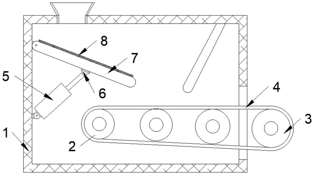
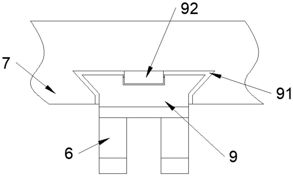
[0023] Please refer to figure 1 , image 3 and Figure 4 As shown, the present invention provides a buffer material receiving device for coal mines, comprising a material receiving box 1, a material inlet is provided at the top of the material receiving box 1, and a material receiving plate 7 and a buffer cylinder 5 are respectively hinged on one side of the inner wall of the material receiving box 1 , the material receiving plate 7 is located at the bottom of the feed port, the bottom of the buffer cylinder 5 is located at the bottom of the material receiving plate 7, the top of the material receiving plate 7 is hinged with a connecting ear 6, the top of the connecting ear 6 is fixedly connected with a slider 9, and the slider 9 The top is rotatably connected with a roller 92, the bottom end of the material receiving plate 7 is provided with a slider 9 matching the slider 9, the slider 9 is slidably connected with the chute 91 through the roller 92, and the inside of the mat...
Embodiment 2
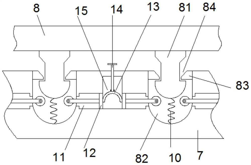
[0026] Please refer to figure 1 and figure 2 As shown, the present invention provides a buffer material receiving device for coal mines. This embodiment adopts the same technical solution as that of the first embodiment. The end is provided with an elastic connector 81, and the top of the material receiving plate 7 is provided with a connecting groove 82 that matches the elastic connector 81. The inner wall of the connecting groove 82 is fixedly connected with a limit ring 83, and the outer side of the elastic connector 81 is provided with a limit ring 83. The matching limit groove 84, the limit ring 83 is engaged with the limit groove 84, and the left and right sides of the connecting groove 82 are provided with piston chambers 11, the piston chambers 11 between the connecting grooves 82 communicate, and the piston chambers 11 A hollow cavity 15 is provided at the upper end of the joint, and a T-shaped extruding plate 12 is slidably connected to the piston cavity 11. The up...
PUM
 Abstract
Description
Claims
Application Information
 - R&D
- Intellectual Property
- Life Sciences
- Materials
- Tech Scout
- Unparalleled Data Quality
- Higher Quality Content
- 60% Fewer Hallucinations
Browse by: Latest US Patents, China's latest patents, Technical Efficacy Thesaurus, Application Domain, Technology Topic, Popular Technical Reports.
© 2025 PatSnap. All rights reserved.Legal|Privacy policy|Modern Slavery Act Transparency Statement|Sitemap|About US| Contact US: help@patsnap.com


