A locking device for preventing misoperation of power system

A technology of anti-misoperation and locking device, which is applied in the direction of circuits, electric switches, electrical components, etc., can solve the problems of electrode sheet damage, irreparable damage, clamping components to electrode sheet damage, etc., to improve frictional resistance and improve firmness , Improving the effect of buffer safety protection performance

Active Publication Date: 2022-07-22
GUANGZHOU POWER SUPPLY BUREAU GUANGDONG POWER GRID CO LTD
View PDF0 Cites 0 Cited by
  • Summary
  • Abstract
  • Description
  • Claims
  • Application Information

AI Technical Summary

Problems solved by technology

Prevent the load from opening and closing the isolating switch; prevent the live wire from hanging (closing) the grounding wire (grounding switch); prevent the grounding wire (grounding switch) from closing the circuit breaker (isolation switch); There are 4 types: mechanical lock, program lock, electrical interlock and electromagnetic lock. These locking methods have played an active role in the anti-mistake work. Practice has proved that the advantages and disadvantages of various traditional locking methods have been fully demonstrated
[0003] When the existing power system anti-misoperation locking device is used for power misoperation protection, when the adjusting component in the locking device drives the clamping component to clamp and move the electrode sheet inside the power button, there is no sense of retention during the movement process , if the slightest slip occurs in the clamping, the damage caused by the clamping component to the electrode sheet is irreparable, and it is easy to cause damage to the electrode sheet inside the power button, resulting in the lack of buffer safety protection measures for the locking device

Method used


Image

  • A locking device for preventing misoperation of power system
  • A locking device for preventing misoperation of power system
  • A locking device for preventing misoperation of power system

Examples


Embodiment 1

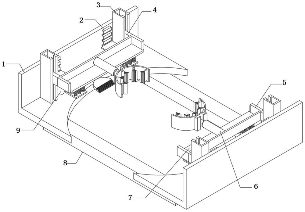
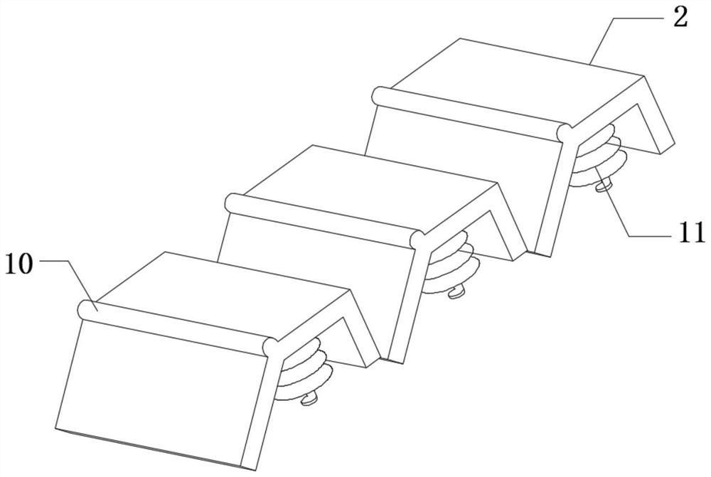
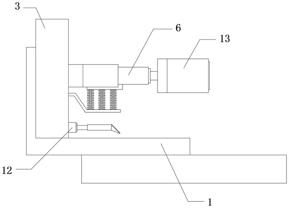
[0033] refer to Figure 1-7 , a latching device for preventing misoperation of an electric power system, comprising a side frame 1, and two limit chutes 3 are fixedly connected to the outer walls of the opposite sides of the two side frames 1, and each limit chutes 3 The inner walls are slidably connected with sliders 4 , the outer walls of the two sliders 4 on the same side frame 1 are fixedly connected with the same fixing frame 5 , and the inner walls on both sides of the fixing frame 5 are fixedly connected with the same adjusting plate 7 , and The bottom outer walls of the two side frames 1 are fixedly connected to the same base 8 , and the outer walls of the side frames 1 close to the two limit chutes 3 are fixedly connected with reciprocating springs 11 at equal distances, and the outer walls of a plurality of reciprocating springs 11 located on the same horizontal plane are fixed. The same level board 2 is connected, and the outer wall of the level board 2 close to the...

Embodiment 2

[0039] refer to Figure 1-8 , a latching device for preventing misoperation of an electric power system, comprising a side frame 1, and two limit chutes 3 are fixedly connected to the outer walls of the opposite sides of the two side frames 1, and each limit chutes 3 The inner walls are slidably connected with sliders 4 , the outer walls of the two sliders 4 on the same side frame 1 are fixedly connected with the same fixing frame 5 , and the inner walls on both sides of the fixing frame 5 are fixedly connected with the same adjusting plate 7 , and The bottom outer walls of the two side frames 1 are fixedly connected to the same base 8 , the outer walls of the side frames 1 close to the two limit chutes 3 are fixedly connected with reciprocating springs 11 at equal distances, and the outer walls of a plurality of buffer springs 11 located on the same horizontal plane are fixed The same level board 2 is connected, and the outer wall of the level board 2 close to the middle turn...


PUM


Abstract

The present invention belongs to the technical field of locking devices, in particular to a locking device for preventing misoperation of power systems. The following solution is now proposed, including side frames. The outer walls on the opposite sides of the two side frames are fixedly connected with two limiting The inner wall of each limit chute is slidably connected with a slider, the outer walls of the two sliders located on the same side frame are fixedly connected to the same fixing frame, and the inner walls on both sides of the fixing frame are fixed The same adjusting plate is connected, and the bottom outer walls of the two side frames are fixedly connected with the same base. In the present invention, a buffer plate and a buffer spring are arranged, and when the clamping ring on the fixing frame is driven by the cylinder to move, the buffer spring shrinks, which has the effect of shock absorption and buffering, and the rebound force of the buffer spring drives the clamping ring to move slightly , so that the buffer plate and the buffer spring can form a progressive fit with the layer plate and the reciprocating spring, so as to further improve the buffer safety protection performance of the locking device.

Description

technical field [0001] The present invention relates to the technical field of locking devices, in particular to a locking device for preventing misoperation of a power system. Background technique [0002] The blocking device mainly refers to: preventing mis-opening and closing the circuit breaker. Prevent the disconnector (isolating switch) with load; prevent live hanging (closing) ground wire (grounding switch); prevent grounding wire (grounding switch) from closing the circuit breaker (isolating switch); There are 4 types: mechanical lock, program lock, electrical interlock and electromagnetic lock. These lock methods have played an active role in preventing misoperation. Practice has proved that the advantages and disadvantages of various traditional lock methods have been fully demonstrated. [0003] When the existing anti-misoperation latching device of the power system is used for protection against power misoperation, when the adjusting component in the latching de...

Claims


Application Information

Patent Timeline
Patent Type & Authority Patents(China)
IPC IPC(8): H01H9/26H01H3/60
CPCH01H9/26H01H3/60
Inventor 刘珍兰冯晓铭陈洁玲廖泽呈余宇轩张晓彤
Owner GUANGZHOU POWER SUPPLY BUREAU GUANGDONG POWER GRID CO LTD
Why Eureka
Try Eureka