An igniter

A technology of igniter and fire source, applied in the direction of combustion ignition, piezoelectric ignition, electrostatic ignition, etc., can solve problems such as danger and difficulty

Active Publication Date: 2021-04-09
沃恩IP私人有限公司
View PDF7 Cites 0 Cited by
  • Summary
  • Abstract
  • Description
  • Claims
  • Application Information

AI Technical Summary

Problems solved by technology

This can lead to difficult and dangerous situations when operating other equipment such as oxy-fuel torches at the same time

Method used


Image

  • An igniter
  • An igniter
  • An igniter

Examples


Embodiment Construction

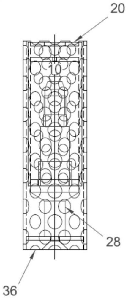
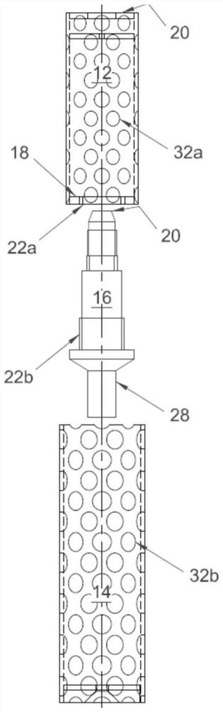
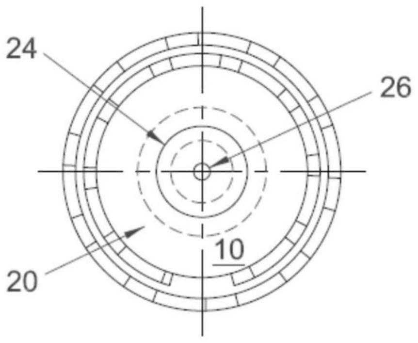
[0055] figure 1 , image 3 and Figure 4 One embodiment of the igniter assembly 10 of the present invention is shown, while figure 2 and Figure 6 An exploded view of the component parts of igniter assembly 10 is shown. figure 2 and Figure 6 Will be discussed in more detail in a later section.

[0056] The igniter assembly 10 may include: an inner holder in the form of an inner tubular member 12 ; an outer housing in the form of an outer tubular member 14 ; and a piezoelectric ignition source 16 . Inner tubular member 12 and outer tubular member 14 generally have a hollow cylindrical shape. While embodiments of the present invention define both the inner and outer tubular members comprising hollow cylindrical shapes, other tubular shapes having different cross-sections are contemplated, such as triangular, square and hexagonal.

[0057] Inner tubular member 12 and outer tubular member 14 are typically made of a heat resistant material such as mild steel. While embod...


PUM


Abstract

An igniter device comprising a holder for a piezo electric ignition source, the holder comprising a first end and a second end, wherein the first end of the inner holder is coupled to a piezo electric ignition source including an actuator, and the second end of the inner holder has a surface configured to receive a tip of an oxy fuel torch; and an attachment means to releasably attach the igniter device to a support member; wherein, the actuator is moveable from a relaxed state to a compressed state to thereby activate the piezo electric ignition source to produce a spark for igniting the oxy fuel torch to produce a flame when the igniter device is attached to the support member.

Description

technical field [0001] The present invention relates to an igniter device for igniting a welding / cutting tool such as an oxy-fuel torch. In particular the invention relates to an igniter device for igniting or re-igniting an extinguished welding / cutting tool or the like. Background technique [0002] There are many different methods of welding / cutting metal, some examples of which are MIG (metal inert gas) welding; arc welding; TIG (tungsten inert gas) welding; FCAW (flux cored arc welding); [0003] Oxy-fuel welding / cutting involves burning a mixture of fuel and oxygen formed by a pressurized flow of fuel and oxygen to create a flame. Combusting fuel in oxygen results in flame temperatures high enough (around 1900°C to 3500°C) to melt metals such as steel, as opposed to burning in air. [0004] Oxy-fuel welding / cutting can be used to cut or weld materials depending on the temperature of the flame, hence the term welding / cutting. [0005] Acetylene is one of the more comm...

Claims


Application Information

Patent Timeline
Patent Type & Authority Applications(China)
IPC IPC(8): F02P3/12F23D14/40
CPCF23Q2/287F23Q3/002F23D14/40F23D14/52H10N30/00F23Q3/008F23Q13/00Y02E20/34F23D2207/00F23Q2/34
Inventor J·R·沃恩
Owner 沃恩IP私人有限公司
Why Eureka
Try Eureka