Feedback design for multi-transmission reception point transmission
A receiving point and coordinated transmission technology, applied in the field of transmission mode, can solve the problems of increasing signaling overhead and delay
- Summary
- Abstract
- Description
- Claims
- Application Information
AI Technical Summary
Problems solved by technology
Method used
Image

Examples
Embodiment Construction
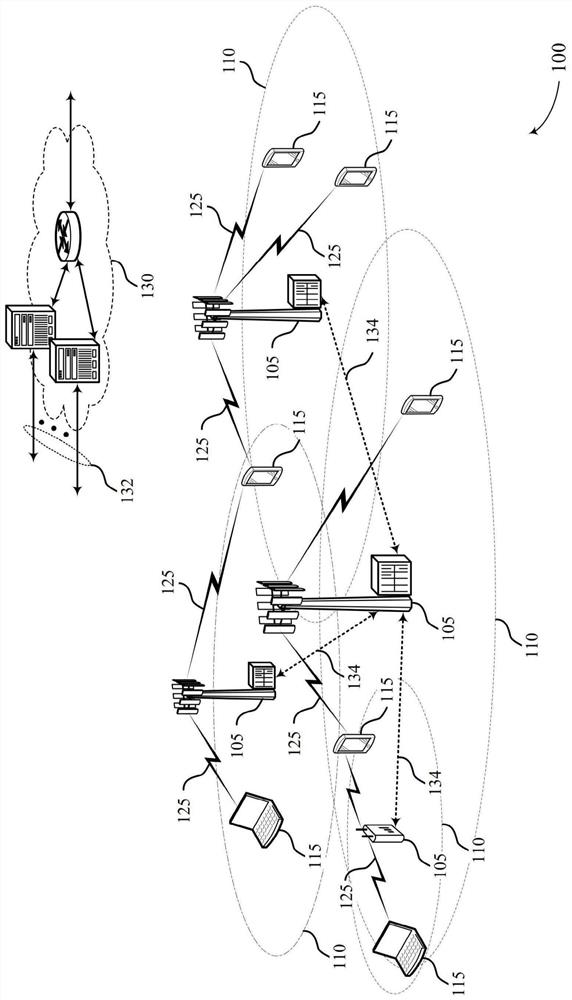
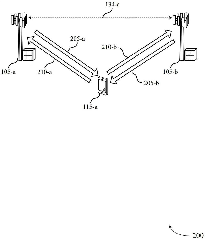
[0064] The described technology relates to an improved method, system, apparatus, or apparatus for supporting feedback design for multi-transmit-receive-point (multi-TRP) transmissions. In general, the described techniques provide for coordinated communication between a set of Transceiver Points (TRPs) and a User Equipment (UE), enabling the UE to coordinate transmission modes based on downlink control signaling and the UE is configured to operate in to identify a configuration for sending feedback to at least one of the TRPs.
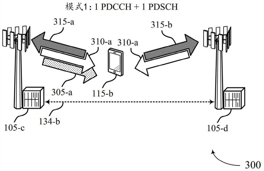
[0065] In an example, the first TRP in the TRP set may send a configuration message for configuring the UE to use the first coordinated transmission mode in a different coordinated transmission mode set to communicate with the TRP set in coordinated transmission. Each coordinated transmission pattern may indicate a number of uplink and downlink control channels and a number of uplink and downlink data channels configured for communication between a par...
PUM
 Abstract
Description
Claims
Application Information