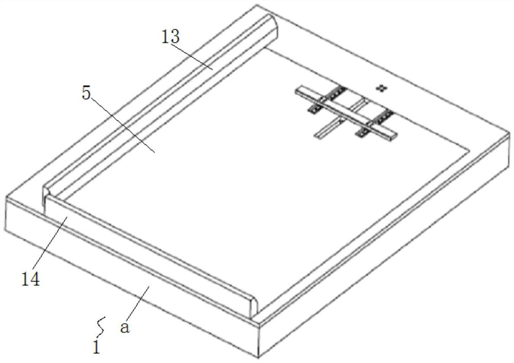
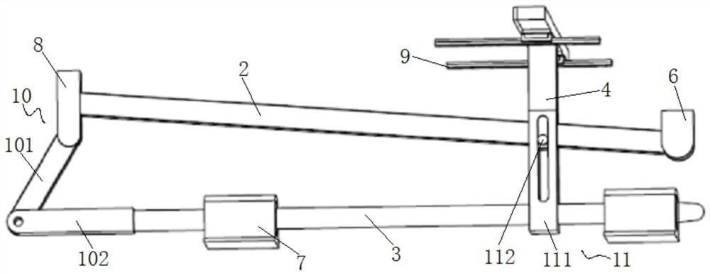
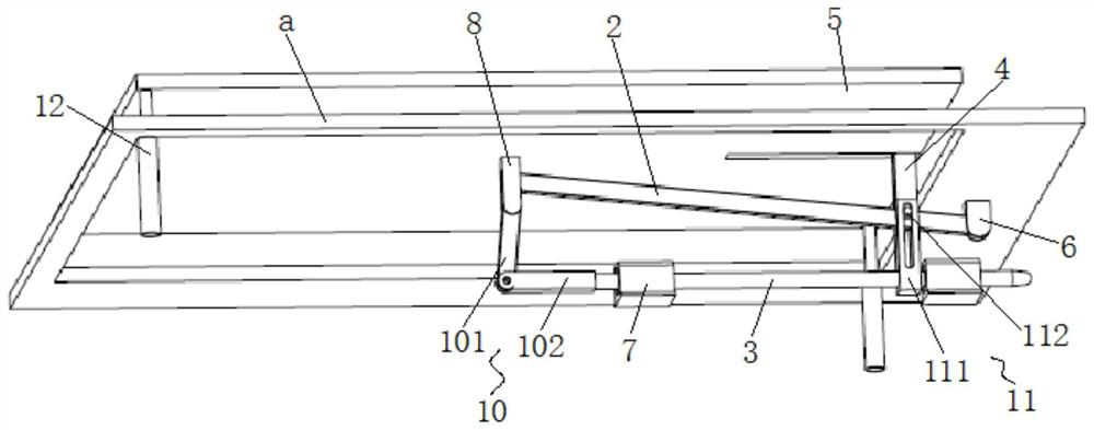
A motherboard positioning and clamping device and motherboard detection equipment

A positioning clamping and main board technology, applied in workpiece clamping devices, optical testing flaws/defects, manufacturing tools, etc., can solve the problems of no positioning method, low efficiency, inconsistency, etc., and achieve the effect of ensuring normality and accuracy

Active Publication Date: 2022-07-01
INSPUR SUZHOU INTELLIGENT TECH CO LTD
View PDF5 Cites 0 Cited by
  • Summary
  • Abstract
  • Description
  • Claims
  • Application Information

AI Technical Summary

Problems solved by technology

[0002] At present, the incoming inspection of main boards is performed manually by personnel. First, there are problems such as long inspection time, slow movement, and low efficiency. Second, errors and omissions have occurred in manual inspection with naked eyes.
However, the introduction of existing automated testing equipment does not have an effective positioning method for the step of placing the main board. They are all manually carried and placed on the carrier board. The carrier board is driven by a motor or cylinder to the designated position, and the camera takes pictures. Analyze and test the process, and launch after the test is completed
However, in actual production, after the main board is placed manually, if no clamping mechanism is added, the main board will be slightly or heavily shifted during the movement with the carrier board. The principle of main board detection is that the camera captures the reflection of the needle. If there is any abnormality, the reflection of the pin will be inconsistent with others. If the position is shifted and skewed, after the light source is illuminated, the reflection of the pin will be inconsistent, which will affect the accuracy of the camera's visual judgment of the detection result, thereby affecting the accuracy of the final result.

Method used


Image

  • A motherboard positioning and clamping device and motherboard detection equipment
  • A motherboard positioning and clamping device and motherboard detection equipment
  • A motherboard positioning and clamping device and motherboard detection equipment

Examples


Embodiment Construction

[0036] In order to make the purposes, technical solutions and advantages of the embodiments of the present invention clearer, the technical solutions of the present invention will be clearly and completely described below with reference to the accompanying drawings. Obviously, the described embodiments are part of the embodiments of the present invention, but not all of them. example. Based on the embodiments of the present invention, all other embodiments obtained by those of ordinary skill in the art without creative efforts shall fall within the protection scope of the present invention.

[0037] The terms "comprising" and "having" mentioned in the embodiments of the present invention and any variations thereof are intended to cover non-exclusive inclusion. For example, a process, method, system, product or device comprising a series of steps or units is not limited to the listed steps or units, but optionally also includes other unlisted steps or units, or optionally also ...


PUM


Abstract

The invention provides a main board positioning and clamping device and main board detection equipment, belonging to the technical field of main board detection related test equipment, and solves the problem that the main board is placed without positioning and clamping, and the main board is skewed in place due to unstable movement process and movement inertia. The problem. It includes a base, a first connecting rod, a guide column, a clamping rib and a liftable mainboard carrier. The base is fixedly provided with a first support and a linear bearing seat, and the lower surface of the mainboard carrier is fixedly provided with The second support, the first end of the first connecting rod is connected with the first support through the rotating shaft, the second end of the first connecting rod is connected with the second support through the rotating shaft, the guide column is The first end is movably connected with the linear bearing seat. The invention optimizes the placement process of the main board, avoids the occurrence of inaccurate detection results caused by the incorrect position of the main board, and adopts a pure mechanical structure, which can basically achieve maintenance-free, long service life and reliable performance.

Description

technical field [0001] The invention relates to the technical field of mainboard detection related testing equipment, in particular to a mainboard positioning and clamping device and a mainboard detection device. Background technique [0002] At present, the detection of incoming motherboard materials is performed manually by personnel. First, there are problems such as long detection time, slow action and low efficiency, and second, errors and omissions have occurred in manual visual inspection. However, the introduction of the existing automatic detection equipment for the placement of the main board has no effective positioning method. All of them are directly transported and placed on the carrier board. The carrier board is driven by the motor or the cylinder to run to the designated position, and the camera takes pictures. Analyze the process of detection, and then launch after the detection is completed. However, in actual production, after the main board is manually ...

Claims


Application Information

Patent Timeline
Patent Type & Authority Patents(China)
IPC IPC(8): G01N21/88B25B11/00
CPCG01N21/88B25B11/00
Inventor 李笑春
Owner INSPUR SUZHOU INTELLIGENT TECH CO LTD
Why Eureka
Try Eureka