Axial flow ventilation or diagonal flow ventilation

An axial flow and diagonal flow technology, applied in the field of rotating wheels, to achieve the effect of reducing noise

Active Publication Date: 2016-12-21
EBM PAPST ST GEORGEN & -
View PDF5 Cites 0 Cited by
  • Summary
  • Abstract
  • Description
  • Claims
  • Application Information

AI Technical Summary

Problems solved by technology

But this kind of turbulence does not make sense for a fast rotating fan, because the flow in a fast rotating fan is inherently turbulent

Method used


Image

  • Axial flow ventilation or diagonal flow ventilation
  • Axial flow ventilation or diagonal flow ventilation
  • Axial flow ventilation or diagonal flow ventilation

Examples


Embodiment Construction

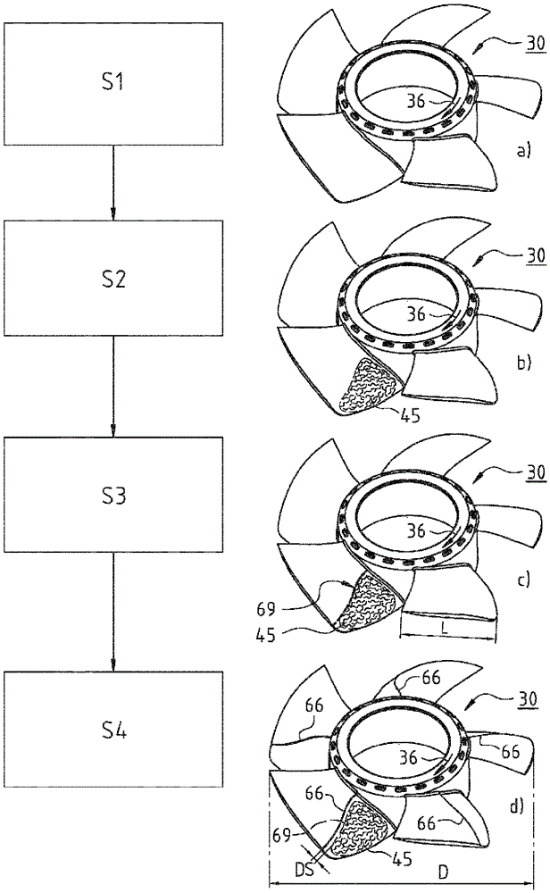
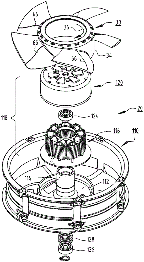
[0019] figure 1 Shown are the main parts of a rotating wheel (ventilator wheel) 30 for an axial fan, for example at Figure 5 is shown in an exploded view.

[0020] In this example, the turning wheel 30 has five turning blades (blades) 32 of a specific profile, which are connected to a hub 34 . The direction of rotation of the rotating wheel 30 is indicated at 36 and in this example moves clockwise when viewing the rotating wheel 30 in the direction of the arrow 38 from above.

[0021] The hub 34 has an opening 40 into which a so-called balancing weight can be inserted during balancing, as soon as an imbalance is determined.

[0022] Since the rotor blades 32 are mostly identical and have the same or similar angular distance from each other, it is sufficient to consider one of the rotor blades 32 in detail, in figure 1 The rotor blade is shown on the lower left in the center. The rotor blades are usually produced together with the hub 34 and the other rotor blades 32 , oft...


PUM


Abstract

An axial- or diagonal-fan has a fan wheel (34) having profiled rotor blades (32). Each blade has a suction or intake side (46), a portion located forward, with respect to the rotation direction (36), and having a leading edge (44), and a portion located rearward, with respect to the rotation direction (36), and having a trailing edge (92). Between said portions, on the intake side (46) of the respective rotor blade (32), a trip or separation edge (66) is provided, said trip edge having an S-shaped contour in a meridian cross-section.

Description

technical field [0001] The invention relates to an axial fan or a diagonal fan with a fan wheel, which is also called a running wheel. Background technique [0002] A boundary layer forms during operation on the suction side of the rotor blade. In a ventilator, the positive pressure gradient generated by the ventilator acts on this boundary layer, and as a result the boundary layer can be separated. The disadvantage of such separation of the boundary layer is higher drag and loss of lift (English: stall). This adversely affects the efficiency of the fan, and its sound emissions increase. [0003] In order to prevent flow separation or to shift the onset of flow separation in the direction of the discharge edge of the associated vane, so-called turbulators have been developed. This concept refers to measures for forcing the transition from laminar to turbulent flow. The advantage of a turbulent boundary layer over a laminar boundary layer is its higher kinetic energy, so ...

Claims


Application Information

Patent Timeline
Patent Type & Authority Patents(China)
IPC IPC(8): F04D29/38F04D29/68
CPCF04D29/384F04D29/681F05D2240/306Y02E10/72
Inventor P.拉格M.施塔德勒
Owner EBM PAPST ST GEORGEN & -
Why Eureka
Try Eureka