A binding device and its control method

A control method and equipment technology, applied in the direction of electrical components, electrical components, etc., can solve the problems of binding equipment affecting the binding accuracy, etc., and achieve the effects of reducing the average running time, reducing the internal vibration amplitude, and reducing the reaction force

Active Publication Date: 2021-12-10
合肥欣奕华智能机器股份有限公司
View PDF14 Cites 0 Cited by
  • Summary
  • Abstract
  • Description
  • Claims
  • Application Information

AI Technical Summary

Problems solved by technology

[0006] A binding device and its control method provided by the embodiments of the present invention aim to solve the problem that the internal vibration caused by the binding device during high-frequency movement affects the binding accuracy

Method used


Image

  • A binding device and its control method
  • A binding device and its control method
  • A binding device and its control method

Examples


Embodiment 1

[0138]The basic scheme of the control method is: control the main motion platform to perform variable speed movement with the first acceleration relative to the first linear guide rail in the positioning step, and the direction of the first acceleration is always opposite to the direction of the second acceleration; wherein, the second Acceleration is the acceleration relative to the second linear guide when the working end is in the positioning step.

[0139] Since the first acceleration of the main motion platform is in the opposite direction to the second acceleration direction of the working end, during the positioning period, by controlling the main motion platform to perform a variable speed movement opposite to the acceleration direction of the working end, the working end and the working end The reaction force of the main motion platform acting on the inside of the binding device is in the opposite direction, that is, the reaction force of the main motion platform can b...

Embodiment 2

[0156] Since the overall mass of the working end is smaller than that of the main motion platform, in order to simplify the control scheme, the influence of the working end on the vibration amplitude inside the binding device can be ignored. At this point, the control method is:

[0157] The main motion platform is controlled to move at a constant speed at a first preset speed on the first linear guide rail in the first binding step, the positioning step and the second binding step. The working end moves at a constant speed at a second preset speed during the first binding step and the second binding step.

[0158] Compared with the technical solution in which the main motion platform and the working end perform variable speed movement in the first positioning step and the second positioning step, the technical solution of this embodiment can simplify the control procedure of the binding equipment, and is more conducive to the control of the binding equipment . It should be ...

Embodiment 3

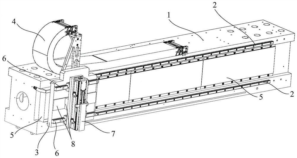
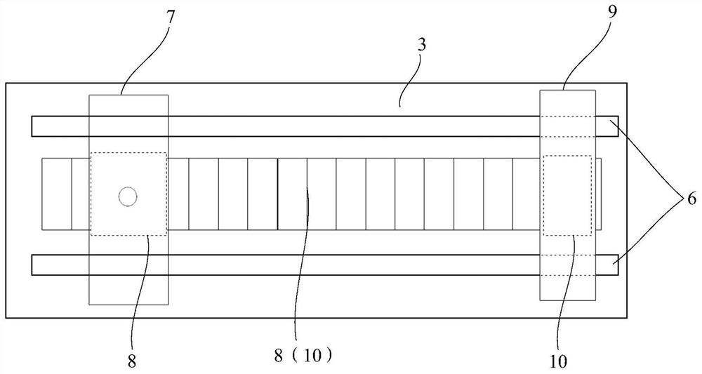
[0173] In order to further reduce the vibration amplitude caused by the reaction force generated during the reciprocating movement of the working end inside the binding device, the main motion platform is controlled on the first linear guide rail in the first binding step, positioning step, and second binding step. On the basis of performing uniform motion at the first preset speed, the binding device also includes:

[0174] The reciprocating end is arranged on the second linear guide rail.

[0175] The third driving device is used to drive the reciprocating end to move on the second linear guide rail, and the control device is also connected to the third driving device.

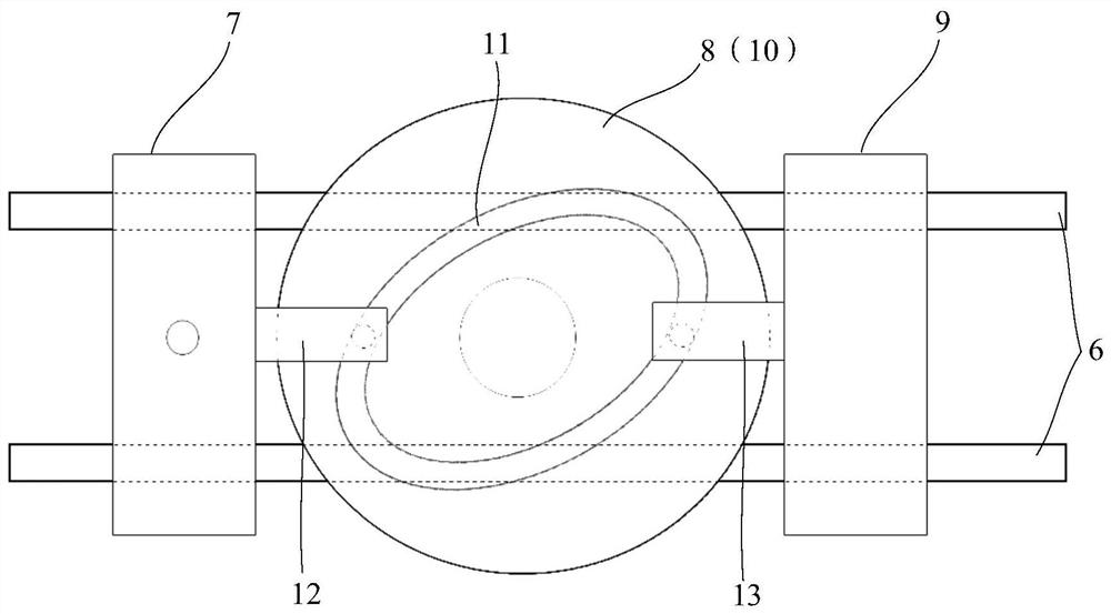
[0176] At this time, the positioning step further includes: controlling the reciprocating end to reciprocate on the second linear guide rail at a third acceleration, and making the direction of the third acceleration always opposite to the direction of the second acceleration.

[0177] Since the direction o...


PUM


Abstract

The invention discloses a binding device and a control method thereof, relates to the field of microelectronic processing equipment, and aims to solve the problem that the internal vibration caused by the binding device during high-frequency movement affects the binding accuracy. The binding device includes: a first linear guide rail, set on the base; a main motion platform, set on the first linear guide rail; a first driving device, used to drive the main motion platform to move; a second linear guide rail, set On the main motion platform, it is set in the same direction as the first linear guide rail; the working end is set on the second linear guide rail, and the overall mass of the working end is smaller than the overall mass of the main motion platform; the second driving device is used to drive the work Terminal movement; the control device is respectively connected with the first driving device and the second driving device, and is used to control the movement of the main motion platform on the first linear guide rail, and control the reciprocating motion of the working end on the second linear guide rail. The invention is used in the processing of microelectronic equipment.

Description

technical field [0001] The invention relates to the field of microelectronic processing equipment, in particular to a binding device and a control method thereof. Background technique [0002] A bonded device is a common device in the semiconductor field. Used to bind dense semiconductor devices in incoming materials to numerous scattered target positions. Among them, the bonding accuracy and bonding frequency (the number of devices bonded per unit time) are the two most critical indicators. [0003] With the rapid development of the industry, while ensuring the binding accuracy, higher requirements are put forward for the binding frequency. During the binding process, the binding device needs to perform a motion process of "translation to the target position - binding - translation to the next target position - binding". Among them, the process of frequent movement from one binding target position to the next target position presents a form of periodic motion, and shorte...

Claims


Application Information

Patent Timeline
Patent Type & Authority Patents(China)
IPC IPC(8): H05K13/04
CPCH05K13/0406H05K13/0495
Inventor 王广炎张作军冯晓庆刘晏何烽光刘正勇
Owner 合肥欣奕华智能机器股份有限公司
Why Eureka
Try Eureka