Efficient cleaning device for squatting pan

A technology for cleaning devices and squatting toilets, which is applied to household cleaning devices, cleaning equipment, household appliances, etc., can solve problems such as low work efficiency, inability to perform cleaning in all directions, time-consuming and labor-intensive, etc., to improve work efficiency and save manpower. Effect

Pending Publication Date: 2021-04-16
吕思建
View PDF8 Cites 0 Cited by
  • Summary
  • Abstract
  • Description
  • Claims
  • Application Information

AI Technical Summary

Problems solved by technology

[0005] In order to overcome the disadvantages of the above-mentioned patents that when cleaning the squatting pan, the device needs to be manually lifted to the squatting pan, which takes time and effort, and cannot be cleaned in all directions, and the work efficiency is low, the technical problem to be solved by the present invention is to provide a A high-efficiency squatting toilet cleaning device that does not need manual lifting devices and can automatically clean squatting toilets

Method used


Image

  • Efficient cleaning device for squatting pan
  • Efficient cleaning device for squatting pan
  • Efficient cleaning device for squatting pan

Examples


Embodiment 1

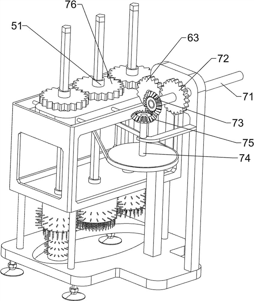
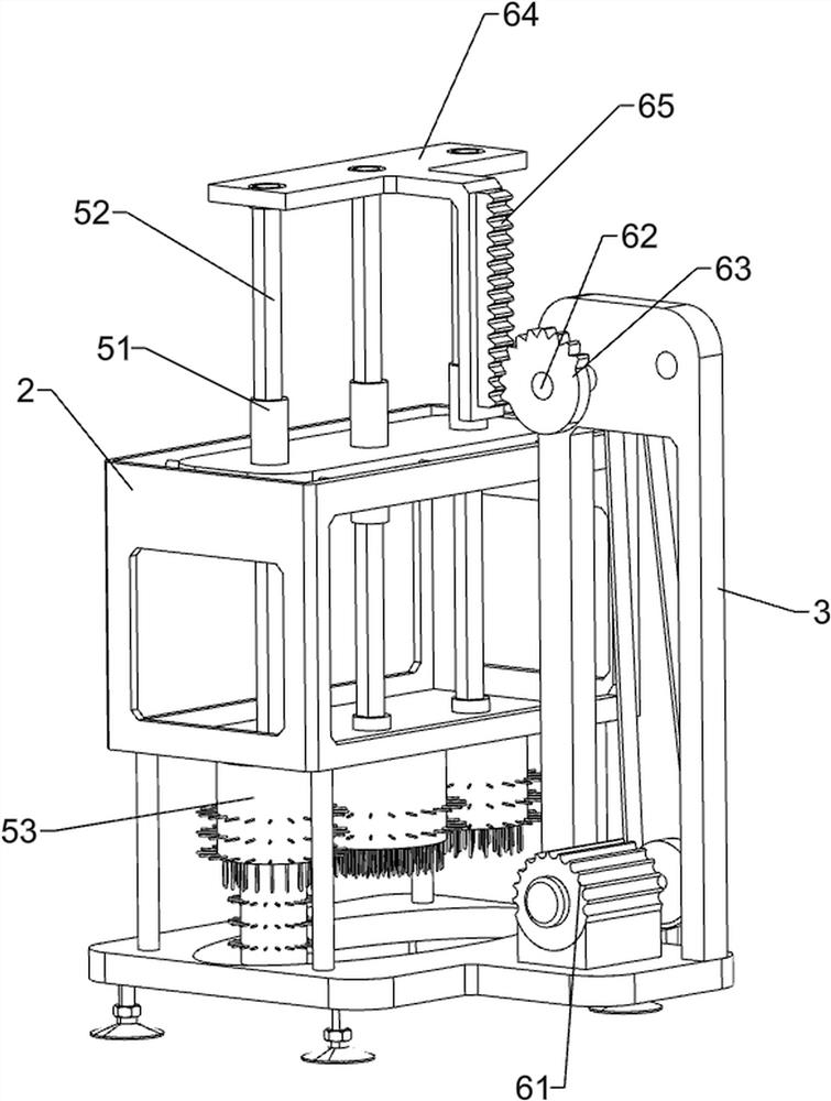
[0024] A squatting toilet efficient cleaning device, such as Figure 1-3 As shown, it includes a base 1, a frame 2, a support plate 3, a slide plate 4, a cleaning assembly 5, a lifting assembly 6, and a rotating assembly 7. The top of the base 1 is connected to the frame 2, and the right side of the top of the base 1 is connected to the support plate 3. The frame 2 The top is connected with a slide plate 4, the bottom of the frame 2 is rotatably connected with a cleaning component 5, the upper part of the support plate 3 is rotatably connected with a lifting component 6, and the upper part of the support plate 3 is rotatably connected with a rotating component 7.

[0025] The cleaning assembly 5 includes a diamond-shaped sleeve 51, a rhombic rod 52 and a hair brush 53. Three diamond-shaped sleeves 51 are rotatably connected to the upper and lower sides of the frame 2, and three diamond-shaped sleeves 51 on both sides are slidably connected to each other. The rhombus rods 52, a...

Embodiment 2

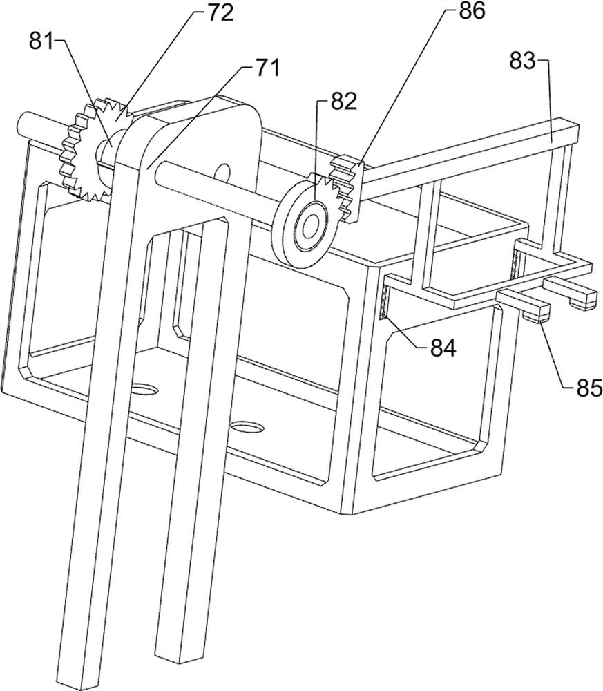
[0030] On the basis of Example 1, such as Figure 4 As shown, it also includes a water discharge assembly 8, the water discharge assembly 8 includes a scroll spring 81, a one-way gear 82, a pressure rod 83, a return spring 84, an action block 85 and a short rack 86, the second rotating shaft 71 and the support plate 3 A scroll spring 81 is connected between them, a one-way gear 82 is connected to the rear end of the second rotating shaft 71, a pressure rod 83 is slidably connected to the rear end of the upper side of the frame 2, and a return spring 84 is sleeved between the pressure rod 83 and the frame 2 , the rear side of the bottom of the depression bar 83 is connected with an action block 85, and the right end of the top of the depression bar 83 is connected with a short rack 86.

[0031] The second rotating shaft 71 rotates the scroll spring 81 and is compressed. When the half gear 63 is disengaged from the first gear 72, the second rotating shaft 71 is reversed by the c...

Embodiment 3

[0033] On the basis of Example 2, such as figure 1 As shown, a sliding assembly 9 is also included. The sliding assembly 9 includes a support plate 91 and a slide bar 92. There are support plates 91 connected to the left and right sides of the wall, and two slide bars 92 are connected between the support plates 91 on both sides. The slide block is slidably connected with two slide bars 92 .

[0034] When people need to clean the squatting pan, the device can be positioned directly above the squatting pan by pushing the slide plate 4, thereby saving a lot of manpower by manually moving the device to the squatting pan.


PUM


Abstract

The invention belongs to a cleaning device, in particular to an efficient cleaning device for a squatting pan. The invention aims to provide the efficient cleaning device which is used for the squatting pan, does not need a manual lifting device and can clean the squatting pan in a full-automatic manner. The efficient cleaning device for the squatting pan comprises a base, a support plate, a sliding plate, a cleaning assembly, a lifting assembly and a rotating assembly; the base is connected with a frame; the support plate is connected to the base; the sliding plate is connected to the frame; the cleaning assembly is rotatably connected to the frame; the lifting assembly is rotationally connected to the support plate; and the rotating assembly is rotationally connected to the support plate. Through cooperation of the cleaning assembly, the lifting assembly and the rotating assembly, the surface of the squatting pan is cleaned, and the squatting pan does not need to be cleaned manually.

Description

technical field [0001] The invention relates to a cleaning device, in particular to a high-efficiency cleaning device for a squatting pan. Background technique [0002] With the development of social technology and the improvement of people's living standards, squatting toilets have become common in every household, and as people are busy, people tend to ignore the hygiene problems of toilets, and only realize it when squatting toilets smell and change color. It is not too easy to clean, and it is time-consuming and laborious to clean, so it is necessary to design a convenient device for automatically cleaning the squatting pan. [0003] After searching, the patent publication number is: CN108478081B patent, which discloses a high-efficiency cleaning device for squatting toilets, including a first threaded rod, the first threaded rod is connected with a driving mechanism, the first threaded rod is threaded with a threaded sleeve, and the threaded sleeve The upper rotation i...

Claims


Application Information

Patent Timeline
Patent Type & Authority Applications(China)
IPC IPC(8): A47L25/00
Inventor 吕思建
Owner 吕思建
Why Eureka
Try Eureka