Folding control surface assembling method

An assembly method and technology for folding rudders, which are used in manufacturing tools, hand-held tools, etc., can solve the problems of peeling off the protective coating on the surface of the rudder surface, unable to find the mounting holes of the rudder surface, and difficult to meet the design requirements, so as to reduce the number of equipment. , Excellent assembly quality and use effect, the effect of improving assembly accessibility

Active Publication Date: 2021-04-16
BEIJING HANGXING MACHINERY MFG CO LTD
View PDF5 Cites 1 Cited by
  • Summary
  • Abstract
  • Description
  • Claims
  • Application Information

AI Technical Summary

Problems solved by technology

[0003] The rudder surface of the folding structure uses a large torque torsion spring as the main driving force of the folding and unfolding mechanism. Since the assembly space is relatively narrow and the assembly contact surface of the front and rear sections of the rudder is longer than the installation surface of the torsion spring, it is impossible to align the rudder when the torsion spring is in a free state. The mounting holes in the rear section of the rudder, so that it is impossible to install the front and rear sections of the rudder in place while the torsion spring is preloaded
[0004] During the assembly process, the torsion spring needs to be pre-loaded into the front section of the rudder, and then the rear section of the rudder surface is used to rotate the torsion spring to a preloaded state, and then push the rear section of the rudder surface to be installed along a straight line while maintaining the preload of the torsion spring For the front section of the rudder, since the assembly contact surface of the front and rear sections of the rudder is a right-angle structure, positioning and clamping must be satisfied at the same time, which is difficult to complete only by the operator's manual work; and frequent knocking and vibration during the assembly process will cause the surface of the rudder surface The peeling off of the protective coating makes it difficult to meet the design requirements and affects the use effect of the final rudder surface

Method used


Image

  • Folding control surface assembling method
  • Folding control surface assembling method
  • Folding control surface assembling method

Examples


Embodiment 1

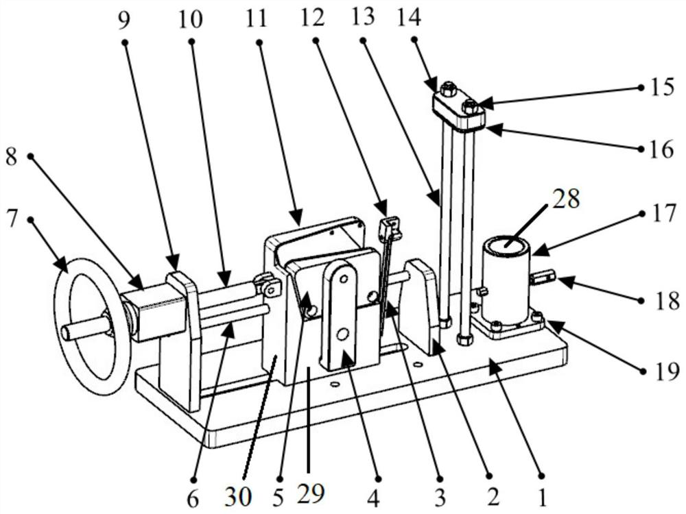
[0078] A specific embodiment of the present invention discloses a rudder surface assembly tool for assembling the front section of the rudder surface and the rear section of the rudder surface. Such as figure 1 As shown, the rudder surface assembly tooling includes a first positioning clamping structure, a second positioning clamping structure, a torsion spring alignment structure and an orientation drive mechanism.

[0079] The structure and function of each part of the rudder surface assembly tool are described in detail below.

[0080] The first positioning and clamping structure is used for positioning and clamping the front section of the rudder, and provides a basis for subsequent structures. The first positioning clamping structure includes a positioning clamping assembly and a first clamping part.

[0081] Such as figure 1 As shown, the positioning and clamping assembly includes a base 1 , a mounting seat 17 , a positioning pin 18 and a screw 19 . The mounting base...

Embodiment 2

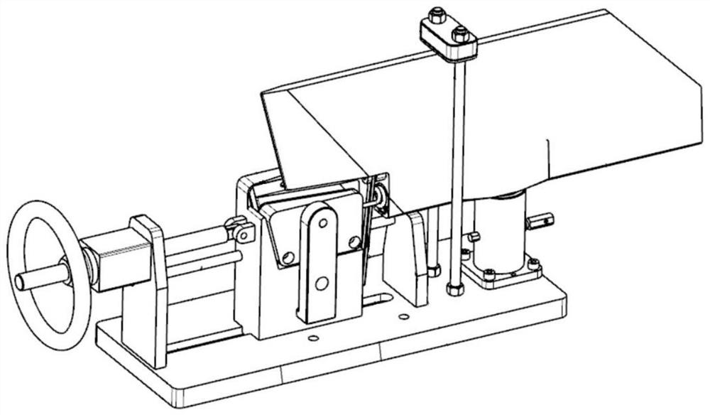
[0102] Another specific embodiment of the present invention discloses a rudder surface assembly method, such as Figure 7 As shown, this assembly method is suitable for the assembly process of the folded structure rudder surface containing torsion spring elements with large torque. Specifically, the assembly method includes the following steps:

[0103] (1) Insert the rotating shaft 27 of the front section of the rudder into the shaft hole of the mounting seat 17, adjust the angular position of the front section of the rudder, and insert the positioning pin 18 to constrain it. During the process of inserting the front section of the rudder, pay attention to avoiding the screw rods 13 on both sides to prevent the screw rods from rubbing rudder surface coating;

[0104] (2) Install the upper platen 16 on the screw rods 13 on both sides, and fix it by nuts 15. Before installation, check whether the rubber pad 14 on the bottom surface of the upper platen 16 exists, and install it...


PUM


Abstract

The invention relates to a folding control surface assembling method, belongs to the technical field of control surface assembling, and solves the problems that in the existing control surface assembling process, the pre-tightening force of a torsion spring is difficult to control and align, the positioning and clamping requirements of front and rear sections of a control surface are high, and the accessibility of manual operation in a narrow space is poor. The folding control surface assembling method comprises the steps that the front section of the control surface is positioned and clamped through a first positioning and clamping structure; a second positioning and clamping structure is adopted for positioning and clamping the rear section of the control surface; a torsion spring positioning piece is inserted into a mounting hole close to the front section of the control surface; a hand wheel lead screw is rotated, so that the control surface rear-section screw hole is aligned with a control surface front-section screw hole; and screws are installed, and installation of the control surface front section and the control surface rear section is completed. A folding control surface assembling tool comprises the first positioning and clamping structure, the second positioning and clamping structure, a torsion spring alignment structure and a directional driving mechanism. Positioning, clamping, relative movement and reliable locking of the front section and the rear section of the control surface are achieved.

Description

technical field [0001] The invention relates to the technical field of rudder surface assembly, in particular to a folding rudder surface assembly method. Background technique [0002] In recent years, with the continuous development and progress of aircraft, the rudder surface is a key component of aircraft attitude adjustment, and its various index parameters have also been continuously improved. [0003] The rudder surface of the folding structure uses a large torque torsion spring as the main driving force of the folding and unfolding mechanism. Since the assembly space is relatively narrow and the assembly contact surface of the front and rear sections of the rudder is longer than the installation surface of the torsion spring, it is impossible to align the rudder when the torsion spring is in a free state. The mounting holes in the rear section of the rudder, so that the front and rear sections of the rudder cannot be installed in place while the torsion spring is prel...

Claims


Application Information

Patent Timeline
Patent Type & Authority Applications(China)
IPC IPC(8): B25B27/30B25B27/14
Inventor 施文昊秦英马兆利
Owner BEIJING HANGXING MACHINERY MFG CO LTD
Why Eureka
Try Eureka