
Chemical quantitative filling machine

A filling machine, chemical technology, applied in the chemical field, can solve the problems of different rates, inaccurate filling amount, etc.

Inactive Publication Date: 2021-04-16
陈培安
View PDF0 Cites 0 Cited by
  • Summary
  • Abstract
  • Description
  • Claims
  • Application Information

AI Technical Summary

Problems solved by technology

[0002] The chemical industry is very strict about the ratio of weight and flow rate. Different chemical products need to go through different ratios of raw materials to achieve the complete generation of chemical reactions. In the process of filling, since the raw materials contain two Different chemical substrates, when feeding, the solid substrate is easy to mix with the liquid raw materials remaining at the feed inlet and form a solid-liquid mixture to block the canning channel, resulting in different material input rates and resulting in inaccurate filling volumes. Based on the above premise , this case developed a chemical quantitative filling machine to solve this problem

Method used


Image

  • Chemical quantitative filling machine
  • Chemical quantitative filling machine
  • Chemical quantitative filling machine

Examples


Embodiment

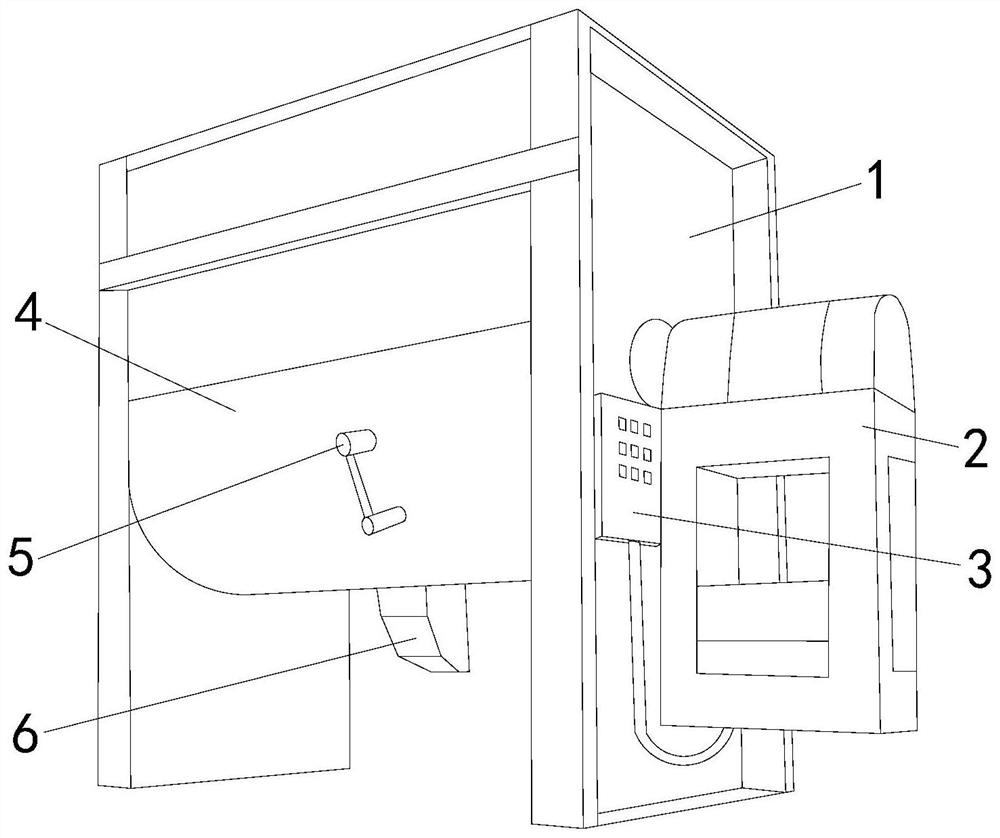
[0024] see figure 1 , the present invention provides a chemical quantitative filling machine, the structure of which includes: a chassis frame 1, a power box 2, a control panel 3, a filling box 4, a stop valve 5, and a liquid outlet 6, and the side of the chassis frame 1 The power box 2 and the control panel 3 are connected. The filling box 4 is located in the chassis frame 1 and is connected with a stop valve 5. The liquid outlet 6 is located at the bottom of the chassis frame 1 and communicates with the filling box 4. The chassis frame 1 The filling box is connected by two plates of equal size. 4 forms the frame structure of the filling machine, and its bottom is at the same level as the ground. As a communication carrier between the power box 2 and the filling box 4, the power lines in the two are connected to each other, relying on the power supply of the power box 2, the filling box 4 has the kinetic energy to realize chemical quantification and process raw material resi...

Embodiment 2

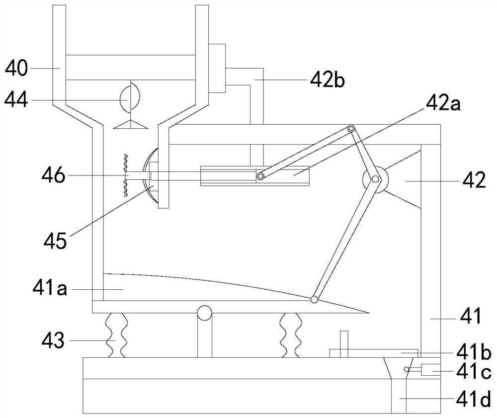
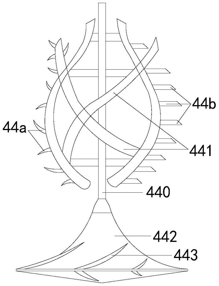
[0030] The description of the second embodiment drawn in conjunction with the first embodiment, combined with figure 2 , image 3 and Figure 5 , the feeding hopper 40 is arranged on the top of the box board 41, the box board 41 is connected with the power arm 42 and is provided with a fixed column 43, the whipping fan shaft 44 is arranged in the feeding hopper 40, and a circulating swivel seat 45 and The crankshaft 46 is thinned and the two are connected to each other. The main shaft 440 is provided with a curved stick frame 441 and its end is connected with a splitter cone 442. The surface of the splitter cone 442 is distributed with diversion grooves 443. Both sides of the vertical shaft 460 are The airfoil 461 is connected and the end is provided with a crushing cone 462. The side of the crushing cone 462 extends outwards to connect with the winding rod 463. In order to avoid the condensate generated by incomplete mixing of chemical materials from blocking the input chan...


PUM


Abstract

The invention discloses a chemical quantitative filling machine which structurally comprises a case frame, a power box, a control panel, a filling box, a check valve and a liquid outlet. The side edge of the case frame is connected with the power box and the control panel, the filling box is located in the case frame and is provided with the check valve to be connected with the case frame, and the liquid outlet is formed in the bottom of the case frame and communicated with the filling box. The chemical quantitative filling machine has the beneficial effects that a whipping fan shaft is used for crushing solids in chemical materials, and therefore the condensate content in the materials is reduced; and meanwhile, a refining crankshaft is used in cooperation to achieve a refining effect on the chemical materials, the mixing speed of the chemical materials is increased while material blockage is avoided, and therefore the quantitative filling accuracy is improved.

Description

technical field [0001] The invention relates to the field of chemical industry, in particular to a chemical quantitative filling machine. Background technique [0002] The chemical industry is very strict about the ratio of weight and flow rate. Different chemical products need to go through different ratios of raw materials to achieve the complete generation of chemical reactions. In the process of filling, since the raw materials contain two Different chemical substrates, when feeding, the solid substrate is easy to mix with the liquid raw materials remaining at the feed inlet and form a solid-liquid mixture to block the canning channel, resulting in different material input rates and resulting in inaccurate filling volumes. Based on the above premise , this case developed a chemical quantitative filling machine to solve this problem. Contents of the invention [0003] Aiming at the deficiencies of the prior art, the present invention is realized through the following t...

Claims


Application Information

Patent Timeline
IPC IPC(8): B65B63/00B65B3/26B65B3/04
Inventor 林小华
Owner 陈培安
Learn More