
A light fixture

A clip-type, light-weight technology, applied in the direction of lifting devices, etc., can solve the problems of large required flow, high working pressure, and small carrying capacity of the whole machine, and achieve the effect of reducing the overall weight and improving synchronization

Active Publication Date: 2022-06-28
HANGCHA GRP +1
View PDF6 Cites 0 Cited by
  • Summary
  • Abstract
  • Description
  • Claims
  • Application Information

AI Technical Summary

Problems solved by technology

However, this type of attachment has disadvantages: the attachment is heavy, the overall height of the attachment is large, the required flow rate is large, and the working pressure is high. It is not suitable for storage stackers and small electric forklifts; , the carrying capacity of the whole machine is small, the clamping action is slow and asynchronous, which does not match the demand for lightweight stacking in storage

Method used


Image

  • A light fixture
  • A light fixture
  • A light fixture

Examples


Embodiment 1

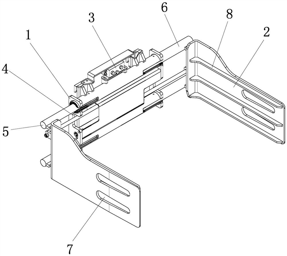
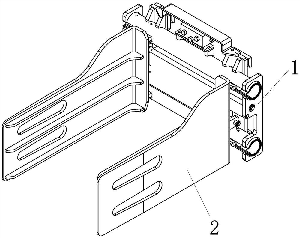
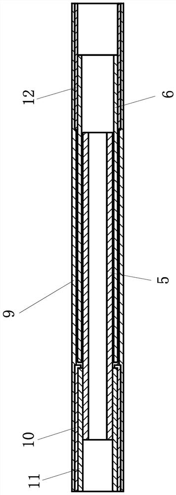
[0025] Example 1: as figure 1 , 2, 3, 4, and 5, a light-duty clip attachment includes a fixed frame 1 and a splint 2 slidably connected to both sides of the fixed frame. A guide rail is arranged inside the fixed frame, and a sliding sleeve rod assembly is arranged inside the guide rail. Each of the splints is connected with the sliding sleeve rod assembly, and the fixing frame is provided with a side shift valve group 3 for driving the sliding sleeve rod assembly to move. The sliding sleeve rod assembly includes a first fixed sleeve 9, a second fixed sleeve, a third fixed sleeve 12, a left guide rod 5 and a right guide rod 6. The second fixed sleeve is located at one end of the first fixed sleeve, and the third fixed sleeve is located on the first fixed sleeve. At the other end of a fixed sleeve, the right guide rod is located in the third fixed sleeve and is slidably connected with the third fixed sleeve, and the left guide rod is located in the second fixed sleeve and is sl...

Embodiment 2

[0027] Embodiment 2: The structure of this embodiment is basically the same as that of Embodiment 1, and the difference is that, such as Image 6 , 7 As shown, the end of the right guide rod close to the left guide rod is provided with a flared portion 14 with a diameter larger than that of the right guide rod. The outer sleeve of the mouth is provided with a sheath 15, the sheath is in the shape of a cone, the free end edge of the sheath is fixedly connected with the free end edge of the flared part, and the other end edge of the sheath is provided with a number of oil outlet grooves 16, the sheath Between the flaring part and the flaring part is an accommodating cavity. The accommodating cavity is embedded with an elastic sleeve 17, a tough sleeve 19 and an oil-absorbing cotton 18. The inner surface of the elastic sleeve is fitted with the outer surface of the flaring part, and the outer surface of the flexible sleeve and the inner surface of the sheath are fitted. Fittingl...


PUM


Abstract

The invention relates to a forklift assembly clamp, in particular to a light-duty clamp attachment. Light-duty clamp attachments include a fixed frame and splints slidingly connected on both sides of the fixed frame. The fixed frame is equipped with a guide rail inside, and the guide rail is equipped with a sliding sleeve rod assembly. Both splints are connected with the sliding sleeve rod group. A side-shift valve group for driving the sliding sleeve rod assembly to move is arranged on the fixed frame. The invention has the beneficial effects of effectively reducing overall weight, stable guiding operation, stronger synchronization and the like.

Description

technical field [0001] The invention relates to a forklift assembling clamp, in particular to a light-duty clamp attachment. Background technique [0002] With the further development of e-commerce logistics, the intensification of warehousing and logistics and lightweighting are the general trend of development. The size and weight of the cargo are relatively small. Storage vehicles are widely used. The left and right clamping arm guide mechanisms are separated, and each moves in its own guide rail. Structural forms are: channel steel structure clamps, T-bar structure clamps, and sleeve clamps. However, this type of attachment has disadvantages: the attachment is heavy, the overall height of the attachment is large, the required flow rate is large, and the working pressure is high, so it is not suitable for assembling storage stackers and small electric forklifts; , The carrying capacity of the whole machine is small, and the clamping action is slow and asynchronous, wh...

Claims


Application Information

Patent Timeline
Patent Type & Authority Patents(China)
IPC IPC(8): B66F9/18B66F9/22
Inventor 杨红宇周迎峰俞佳炜章鸿楠朱振雄
Owner HANGCHA GRP
Learn More