Electrical cabinet with separable protective threading plate

A technology for electrical cabinets and protective wires, applied in the field of electrical cabinets, can solve the problems of dust entering the electrical cabinet, pipeline sliding, pipeline clamping, etc., and achieves the effect of facilitating the threading operation, increasing the operating space, and improving the threading efficiency.

Inactive Publication Date: 2021-11-23
段文洪
View PDF1 Cites 0 Cited by
  • Summary
  • Abstract
  • Description
  • Claims
  • Application Information

AI Technical Summary

Problems solved by technology

[0005] The purpose of the present invention is to provide an electrical cabinet with a detachable protective threading plate, to solve the problem that the existing threading plate proposed in the above background technology is generally a perforated plate structure, and threading is carried out through holes during use. The operation is difficult, and at the same time, it is difficult to clamp the pipeline, which is easy to cause the pipeline to slide, the protection effect of the pipeline is not good, and the dust is easy to enter the electrical cabinet from the opening

Method used


Image

  • Electrical cabinet with separable protective threading plate
  • Electrical cabinet with separable protective threading plate
  • Electrical cabinet with separable protective threading plate

Examples


Embodiment 1

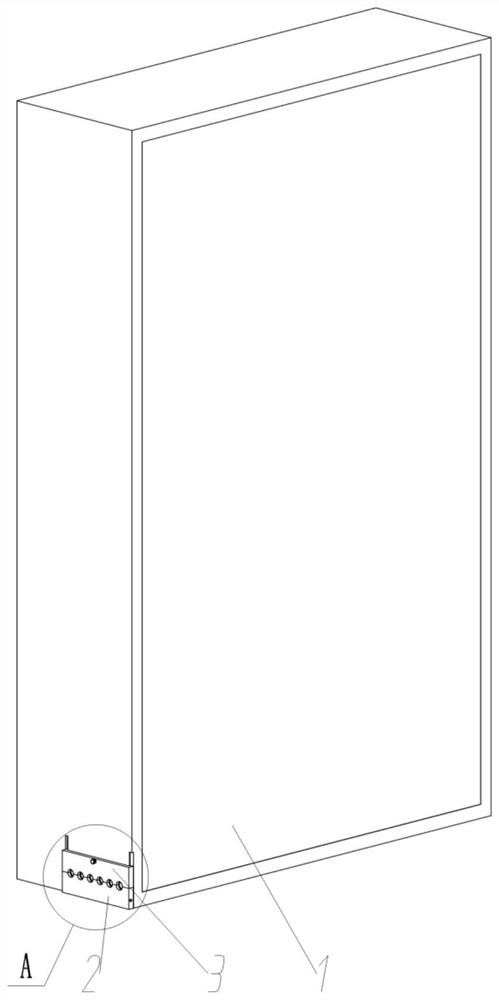
[0060] see Figure 1 to Figure 10 , an embodiment provided by the present invention: an electrical cabinet with a detachable protective wiring board, including an electrical cabinet main body 1;

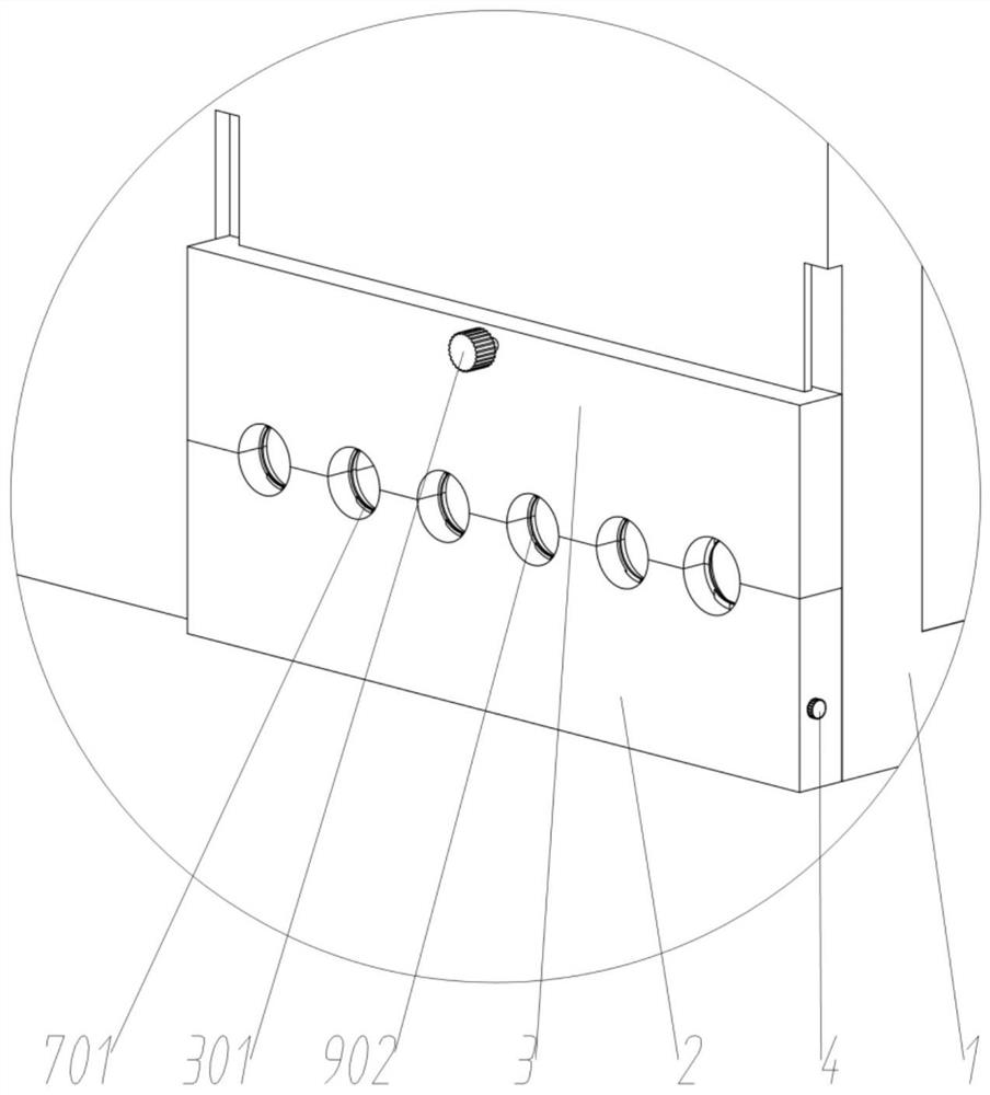
[0061] Fix the protective line plate 2, and the fixed protective line plate 2 is fixedly connected to the lower left side of the main body 1 of the electrical cabinet;

[0062] The movable protective wire plate 3 is slidably connected to the lower left side of the electrical cabinet main body 1;

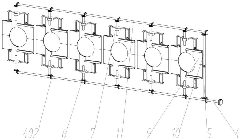
[0063] There are twelve groups of vertical protection plates 7, six groups of vertical protection plates 7 are evenly arranged and slidably connected to the upper part of the fixed protection line plate 2, and the remaining six groups of vertical protection plates 7 are evenly arranged Slidingly connected to the bottom of the movable protective wire plate 3;

[0064] Vertical protection drive mechanism, the vertical protection drive mechanism is arranged on the inner side of the fixed pro...

Embodiment 2

[0075] The top of the lower synchronous transmission shaft 5 and the bottom of the movable synchronous connecting rod 10 are fixedly connected with magnets. In use, the current synchronous transmission shaft 5 is in contact with the movable synchronous connecting rod 10, and the lower synchronous transmission shaft is assisted by magnets. 5 is connected with the movable connecting rod 10 to improve the convenience of use.


PUM


Abstract

The invention discloses an electrical cabinet with a separable protective threading plate, relates to the technical field of electrical cabinets, and solves the problems that an existing threading plate is generally of a perforated plate-shaped structure, threading is performed through a hole in use, the threading operation difficulty is higher, meanwhile, a pipeline is difficult to clamp, the pipeline is prone to sliding, the protection effect of the pipeline is poor, and the dust enters into the electrical cabinet easily through the hole. The electrical cabinet comprises an electrical cabinet main body; a fixed protection wire plate which is fixedly connected to the lower part at the left side of the electrical cabinet main body; and a movable protection wire plate which is connected to the lower part at the left side of the electrical cabinet main body in a sliding manner. According to the present invention, the synchronous sliding of a vertical protection plate and a transverse protection plate is achieved, the size of a threading hole is adjusted, the installation requirements of pipelines with different diameters are met, the pipelines are clamped through the vertical protection plate and the transverse protection plate, the sliding of the pipelines is effectively avoided, dust is effectively prevented from entering the pipeline through the protection of the vertical protection plate and the transverse protection plate, and the protection effect is improved.

Description

technical field [0001] The invention relates to the technical field of electrical cabinets, in particular to an electrical cabinet with a detachable protective wiring board. Background technique [0002] The electrical cabinet refers to the cabinet used to protect the normal operation of electrical components. During the use of the electrical cabinet, in order to facilitate the installation and use of pipelines, protective wiring boards are generally installed. [0003] For example, application number: CN201510789643.3 The present invention relates to a cooling device for an electrical cabinet and an electrical cabinet using the device. The heat dissipation device of the electrical cabinet includes a suction module for being arranged above at least one equipment installation position in the cabinet, and the suction module includes a support for fixing relative to the cabinet and a wind guide buckled above the support The wind guide cover has a downward air suction port and ...

Claims


Application Information

Patent Timeline
IPC IPC(8): H02B1/20H02B1/28
CPCH02B1/202H02B1/28
Inventor 段文洪
Owner 段文洪
Why Eureka
Try Eureka