A public toilet with disinfection function for municipal use

A technology for public toilets and utensils, applied in disinfection, sanitary equipment for toilets, separation methods, etc., can solve the problems of toilet odors that cannot be eliminated, people who go to the toilet are uncomfortable, and airtight, so as to improve the effect of air evolution and reduce infection. Possible Effects of Viruses

Active Publication Date: 2022-07-15
河北雄安唐杰环境科技有限公司
View PDF0 Cites 0 Cited by
  • Summary
  • Abstract
  • Description
  • Claims
  • Application Information

AI Technical Summary

Problems solved by technology

[0003] In public toilets, due to the large flow of people, the excrement of people who come to the toilet is prone to breed viruses. If disinfection is not carried out in time, it may cause the virus infection of people who go to the toilet and cause harm to the body. Most of the current public toilets It is sealed and in an airtight state, so the peculiar smell in the toilet cannot be eliminated, and it will cause discomfort to the people who go to the toilet. How to solve these problems is what we need to consider

Method used


Image

  • A public toilet with disinfection function for municipal use
  • A public toilet with disinfection function for municipal use
  • A public toilet with disinfection function for municipal use

Examples


Embodiment 1

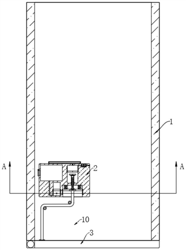
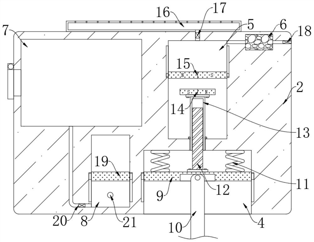
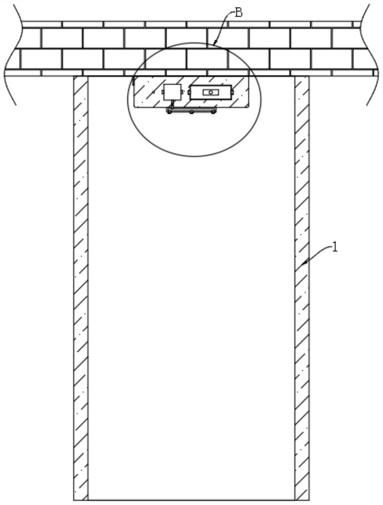
[0025] refer to Figure 1-4 , a public toilet with disinfection function for municipal use, comprising a compartment body 1, the compartment body 1 is arranged at the lower end of the ceiling, the compartment body 1 is provided with a housing 2, and the upper end of the housing 2 is installed on the lower end surface of the ceiling The front side wall of the casing 2 is provided with a moving groove 4, and the casing 2 is provided with a liquid storage cavity 7, a rotating cavity 5 and a filtering cavity 6 in order from left to right. The liquid storage cavity 7, the rotating cavity 5 and the filtering cavity 6 are located on the rear side of the moving groove 4, and the housing 2 is provided with a reciprocating cavity 8, and the reciprocating cavity 8 is located on the left side of the moving groove 4;

[0026] Triggering mechanism, the triggering mechanism includes a first magnetic plate 9 horizontally arranged in the moving groove 4, the first magnetic plate 9 is slidably ...

Embodiment 2

[0032] refer to Figure 5-7 The difference between this embodiment and Embodiment 1 is that two fixed blocks 24 are symmetrically and fixedly connected to the lower end of the housing 2 , and both of the two fixed blocks 24 are provided with a disturbance cavity 25 , and both of the two disturbance chambers 25 are provided with There is a slider 26 for moving back and forth, one end of the ventilation pipe 31 away from the reciprocating cavity 8 is connected with the front side space of the two disturbance chambers 25, and the rear ends of the two sliders 26 are fixedly connected with a rack 27. The rear space of the cavity 25 is vertically provided with a rotating rod 28 , the upper ends of the two rotating rods 28 are rotatably connected with the inner top of the corresponding disturbance cavity 25 , and the lower ends of the two rotating rods 28 penetrate through the corresponding disturbance cavity 25 . The inner bottom is fixedly connected with a plurality of perturbation...


PUM


Abstract

The invention discloses a public toilet with disinfection function for municipal use, comprising a ceiling, a compartment body is fixedly connected to the lower end of the ceiling, a casing is fixedly connected to the lower end of the ceiling, and a front side wall of the casing is opened There is a moving tank. The casing is provided with a liquid storage cavity, a rotating cavity and a filtering cavity in sequence from left to right. The liquid storage cavity, the rotating cavity and the filtering cavity are all located on the back side of the moving tank. Reciprocating cavity, the reciprocating cavity is located on the left side of the moving groove. The device disinfects the toilet when someone enters or leaves the toilet, reducing the possibility of people going to the toilet contracting viruses, and also purifies the air in the toilet and removes the peculiar smell in the toilet. People will not feel uncomfortable because of the odor.

Description

technical field [0001] The invention relates to the field of municipal toilets, in particular to a public toilet with disinfection function for municipal use. Background technique [0002] Municipal facilities refer to various buildings, structures, and equipment that are set up within the planning and construction scope of urban areas and towns and provide residents with paid or unpaid public products and services based on government responsibilities and obligations. Public toilets are a type of municipal facilities. For public toilets, there are the following problems: [0003] In public toilets, due to the large flow of people, the excrement of people who come to the toilet is easy to breed viruses. If it is not disinfected in time, it may cause the virus infection of people who go to the toilet and cause harm to the body. Most of the public toilets today It is sealed and in an airtight state, so the odor in the toilet cannot be eliminated, and it will cause discomfort t...

Claims


Application Information

Patent Timeline
Patent Type & Authority Patents(China)
IPC IPC(8): E04H1/12E03D9/00B01D53/04A61L2/18A61L2/26A61L9/014A61L9/16A61L101/22
Inventor 郑占强
Owner 河北雄安唐杰环境科技有限公司
Why Eureka
Try Eureka