
Fault Diagnosis Method and Diagnosis System of Engine Temperature Control Module

A temperature control module and fault diagnosis technology, applied in engine cooling, engine components, machine/engine, etc., can solve problems such as increasing complexity, ECU unable to judge intermediate state, thermostat unable to carry out self-diagnosis, etc., to achieve retention functional effect

Active Publication Date: 2022-05-27
GUANGZHOU AUTOMOBILE GROUP CO LTD
View PDF0 Cites 0 Cited by
  • Summary
  • Abstract
  • Description
  • Claims
  • Application Information

AI Technical Summary

Problems solved by technology

However, traditional thermostats cannot perform self-diagnosis, and if self-diagnosis is required, an additional water temperature sensor needs to be combined
That is, it is necessary to judge whether the value of the main water temperature sensor has risen normally over time. After it rises to the melting threshold of the thermostat wax bag, it is also necessary to combine the auxiliary water temperature sensor to judge whether the water temperature in the current radiator passage has a normal change. To judge whether the thermostat can be opened or closed normally, in addition, it is also necessary to judge whether the water temperature is normal based on the current vehicle working conditions, that is, the thermostat cannot complete this process by itself, and needs to rely on other components through complex control strategies To realize the diagnosis, especially in the condition of the engine not working on the hybrid model, the complexity of this strategy will increase significantly
Furthermore, since the traditional thermostat only has two states of on or off, the ECU cannot judge the intermediate state. Once a fault causes the water temperature to be too high, it often only makes the whole vehicle limp.

Method used


Image

  • Fault Diagnosis Method and Diagnosis System of Engine Temperature Control Module
  • Fault Diagnosis Method and Diagnosis System of Engine Temperature Control Module

Examples


Embodiment Construction

[0037] The specific embodiments of the present invention will be described in further detail below with reference to the accompanying drawings and embodiments. The following examples are intended to illustrate the present invention, but not to limit the scope of the present invention.

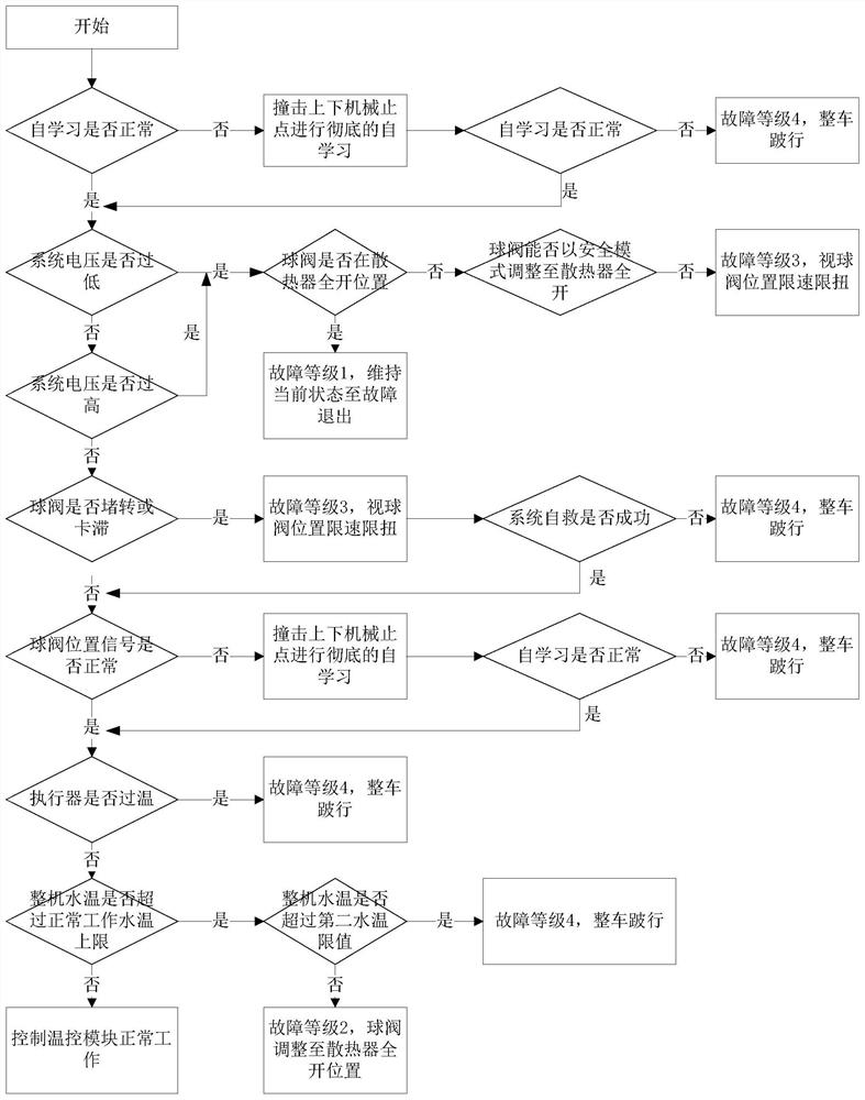
[0038] like figure 1 As shown, the fault diagnosis method of the engine temperature control module provided by the embodiment of the present invention includes:

[0039] Step S10: After the engine is started, self-learning of the temperature control module is performed.

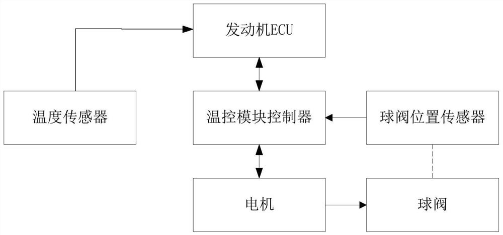
[0040] In step S10, after the engine is started, the engine ECU sends a signal to the temperature control module controller, and the temperature control module controller starts the temperature control module self-learning after receiving the signal. When the temperature control module is self-learning, it is to check whether the stroke of the ball valve meets the design value without hitting the upper and lower dead centers...


PUM


Abstract

A fault diagnosis method for an engine temperature control module, comprising: judging whether the system voltage is within the allowable range in the normal working mode of the temperature control module; if the system voltage is outside the allowable range, outputting a fault code, and Take corresponding countermeasures; if the system voltage is within the allowable range, calculate the equivalent voltage based on the system voltage, and judge whether the current equivalent voltage is less than the set safety threshold; if the current equivalent voltage reaches or exceeds the safety threshold, It is further judged whether the continuous working time of the temperature control module exceeds the limit time; if it exceeds the limit time, the action of the ball valve is forcibly stopped, and the rotation of the ball valve is continued after waiting for the set time. The invention also provides a fault diagnosis system of the engine temperature control module.

Description

technical field [0001] The invention relates to an engine water cooling system, in particular to a fault diagnosis method and a diagnosis system for an engine temperature control module. Background technique [0002] At present, the commonly used engine cooling system on the market usually includes a mechanical water pump and a thermostat. The physical structure of the thermostat is mainly based on the wax pack. When the water temperature is low, the wax pack is solid. The thermostat valve closes the branch of the coolant leading to the radiator under the action of the spring. When the water temperature is high, the wax pack melts into a liquid. , the volume increases accordingly, push the thermostat valve to open the radiator branch to cool down. This structure determines that the engine cooling system can only be switched in two states of a large cycle (with the radiator participating) and a small cycle (with the radiator not participating), and cannot control more branch...

Claims


Application Information

Patent Timeline
Patent Type & Authority Patents(China)
IPC IPC(8): F01P11/14
Inventor 林承伯乔艳菊陈强张旭董春艳吴广权
Owner GUANGZHOU AUTOMOBILE GROUP CO LTD
Learn More