
Test tube detection device and test tube detection method

A test tube detection and test tube technology, which is applied in the direction of measuring devices, test tube holders/clamps, and the counting of items shipped by conveying devices, etc. The detection process is convenient and the effect of a wide range of applications

Inactive Publication Date: 2021-04-16
深圳市爱康生物科技股份有限公司
View PDF5 Cites 0 Cited by
  • Summary
  • Abstract
  • Description
  • Claims
  • Application Information

AI Technical Summary

Problems solved by technology

[0002] At present, the test tube rack assembly line in medical equipment usually needs to be equipped with a test tube detection device to detect the presence or absence of test tubes on the test tube racks transmitted on the assembly line, the test tube slots where the test tubes are located, and the number of test tubes loaded in the test tube racks. The test tube detection scheme includes the use of mechanical movement devices to touch the test tube or the traditional stepping detection method. Due to the large flow of test tubes on the assembly line, the above-mentioned solutions put forward higher requirements for the positioning and detection speed of the test tube. , when the positioning is slightly deviated or the speed does not meet the expected requirements, there is a high possibility of misjudgment, and it is difficult to detect the test tube slot where the test tube is located

Method used


Image

  • Test tube detection device and test tube detection method
  • Test tube detection device and test tube detection method
  • Test tube detection device and test tube detection method

Examples


Embodiment 1

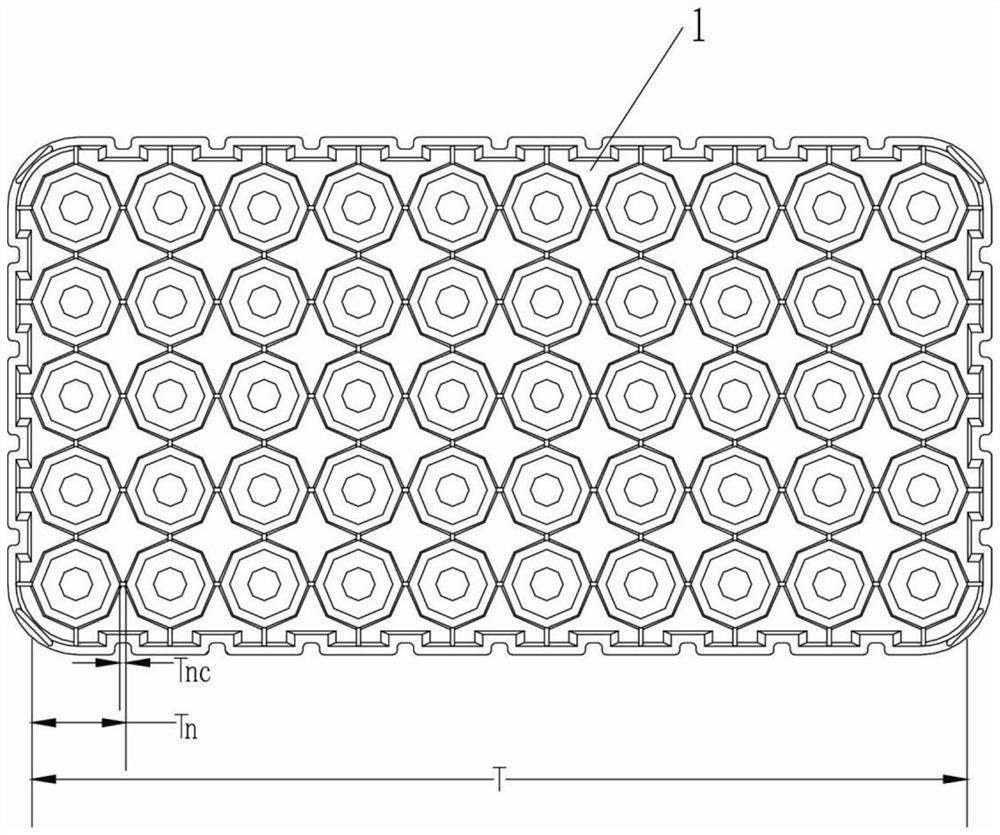
[0073]Example 1: The first two test tube grooves in the single column tube are not loaded, and the remaining tube grooves are loaded with the test tube, and according to the above method, the test tube detection module detects the test tube within TN × 3 time, which will be detected from the third test tube. Start re-timing, continue moving, when arriving at the start position of the fourth test tube, passing time is Tn, then in TN × 3 ~ (TN × 4-TNC) time, TN × 3 ~ (TN × 4-TNC) is equivalent to the passage of the fourth test tube cap because the fourth test tube is loaded with the fourth test tube, so the accumulation is TN + (TN-TNC) = (Tn × 2-TNC) Until the last 10th test tube, the accumulation is final (Tn × 8-TNC), and finally the time is the third test tube to the 10th test tube.

Embodiment 2

[0074]Example 2: Two tube grooves of the single row tube groove unloading tube (i.e., the fifth and sixth test tube grooves are not loaded), and the remaining tube grooves are loaded with the test tube, followed by the above method, the test tube detection module in TN × The test tube was detected in 1 time, starting timing, the time accumulated at the start of the fifth test tube is Tn × 4, and then passing the fifth tube groove during Tn × 4 ~ (Tn × 5-TNC) At this time, at this time, the test tube detection module did not detect the test tube, and did not make time accumulation. The six test tube groove was not loaded. When it was not accumulated, until the seventh test pipe groove was reached, the test tube was detected, and the test tube was detected, and when the finals were started The 10th test tube is (TN × 8-TNC) at the time of accumulation.

Embodiment 3

[0075]Example 3: The last two test tube grooves of the single row tube groove are not loaded with the test tube (ie, the ninth and 10th test tube grooves are not loaded. The remaining test tube grooves are loaded with the test tube, followed by the above method, and the accumulation is finally To (TN × 8-TNC).

[0076]Step 207: Analyze the number of test tubes loaded by the test tube rack at the current column of the test tube groove according to the accumulation timing.

[0077]Step 208, the number of test tubes loaded by each test tube detection module is accumulated to obtain the total number of test tubes loaded by the current test tube frame.

[0078]Such asFigure 6 As shown in an embodiment, the data processing analysis module analyzes the working method of the number of test tubes, as well as:

[0079]In step 209, the test tube is divided into three aliquots by the time of the test tube detection module, and the detection of three detection, two or more, confirmed that the current test t...


PUM


Abstract

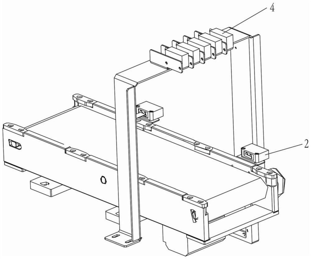
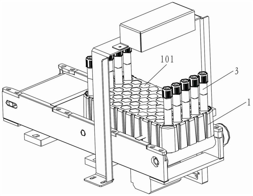
The invention relates to the technical field of test tube detection, and discloses a test tube detection device and a test tube detection method, the test tube detection device comprises a test tube rack, a driving device, a test tube rack detection module arranged opposite to the side surface of the test tube rack, a plurality of test tube detection modules located at the top of the test tube rack and arranged corresponding to test tube grooves for loading test tubes, and a data processing and analyzing module. The test tube detection method of the test tube detection device and comprises data proofreading and test tube detection. The invention aims to provide the test tube detection device and the test tube detection method, so as to provide a test tube detection scheme which can detect the presence or absence of test tubes on a test tube rack conveyed on an assembly line, the positions of test tube grooves where the test tubes are located and the number of test tubes loaded on the test tube rack, and is relatively high in detection accuracy.

Description

Technical field[0001]The present invention relates to the field of test tube detection, and more particularly to a test tube detecting device and a test tube detection method.Background technique[0002]At present, the test tube detecting device in the medical device is usually required to provide a test tube detecting device, and the test tube on the test tube on the pipeline transmitted on the pipeline is detected, and the number of test tube grooves loaded in the test tube is detected. The test tube detection scheme, including the use of mechanical moving devices to touch the tube or conventional stepping detection mode, due to large test tube flow on the pipeline, the above programs, the positioning of the test tube, high requirements When the positioning slightly deviation or speed does not meet the expected requirements, it is possible to detect the test tube groove at the test tube.Inventive content[0003]It is an object of the present invention to provide a test tube detecting ...

Claims


Application Information

Patent Timeline
Patent Type & Authority Applications(China)
IPC IPC(8): G01D21/02B01L9/06G06M7/04
Inventor 李尧江胜标黄振有刘添荣赖鹏飞李运奇
Owner 深圳市爱康生物科技股份有限公司
Learn More