
Touch display panel and touch display device

A touch display panel and display area technology, applied in instruments, organic semiconductor devices, semiconductor devices, etc., can solve problems such as increased contact resistance of touch traces and transfer traces, affecting touch performance, etc.

Pending Publication Date: 2021-04-16
WUHAN TIANMA MICRO ELECTRONICS CO LTD
View PDF0 Cites 8 Cited by
  • Summary
  • Abstract
  • Description
  • Claims
  • Application Information

AI Technical Summary

Problems solved by technology

Because some inorganic layers in the display panel are generally formed by chemical vapor deposition (CVD) process, when the frame of the display panel is narrow, the border of CVD may cover the transfer hole, resulting in the gap between the touch trace and the transfer trace. Increased contact resistance affects touch performance

Method used


Image

  • Touch display panel and touch display device
  • Touch display panel and touch display device
  • Touch display panel and touch display device

Examples


Embodiment Construction

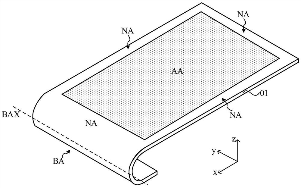
[0032] The present invention will be further described in detail below in conjunction with the accompanying drawings and embodiments. It should be understood that the specific embodiments described here are only used to explain the present invention, but not to limit the present invention. In addition, it should be noted that, for the convenience of description, only some structures related to the present invention are shown in the drawings but not all structures.

[0033] Terms used in the embodiments of the present invention are only for the purpose of describing specific embodiments, and are not intended to limit the present invention. It should be noted that the orientation words such as "up", "down", "left", and "right" described in the embodiments of the present invention are described from the angles shown in the drawings, and should not be interpreted as a reference to the implementation of the present invention. Example limitations. Also in this context, it also nee...


PUM


Abstract

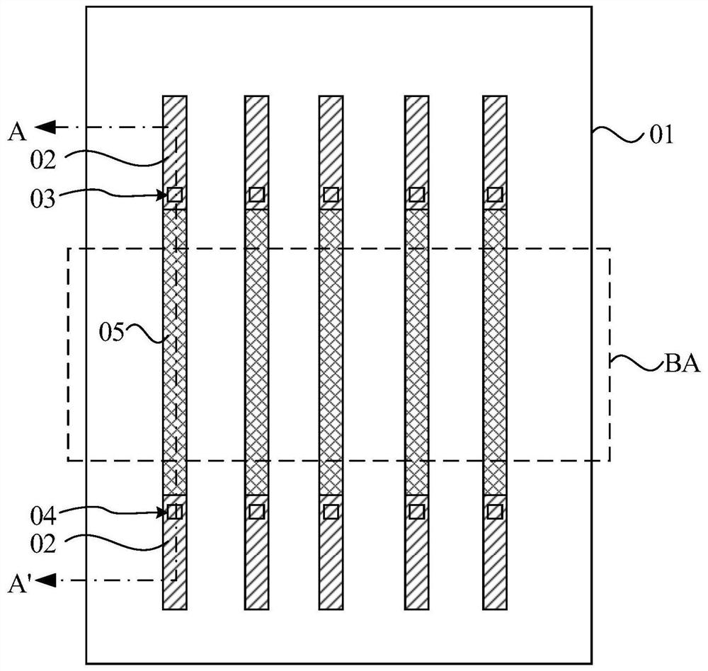
The embodiment of the invention discloses a touch display panel and a touch display device. The touch display panel comprises: a substrate including a display area and a non-display area; a light emitting device located in the display area; a packaging layer which covers the light-emitting device and at least part of the non-display area; a touch layer which is located on the side, away from the light-emitting device, of the packaging layer, and comprises a plurality of touch electrodes; and a plurality of touch control wires which are directly and electrically connected with the touch control electrodes, and extend to the non-display area; wherein the non-display area comprises a first area and a second area, a through hole and / or a groove are / is formed in at least part of the film layer in the first area, the touch wire extends along the surface of the first area and extends to the second area, and the second area is located on the side, away from the display area, of the first area. According to the technical scheme of the embodiment of the invention, the resistance can be prevented from being increased during touch wiring, and the touch performance is improved.

Description

technical field [0001] The embodiments of the present invention relate to the field of display technology, and in particular, to a touch display panel and a touch display device. Background technique [0002] Since touch operation is a simple and convenient way of human-computer interaction, more and more products integrate the touch function into the display panel. According to the structure, the touch panel can be divided into Add on Mode Touch Panel, On Cell Touch Panel and In Cell Touch Panel. Among them, the in-cell touch panel is to arrange the touch electrodes of the touch panel inside the display panel, which can reduce the overall thickness of the module and greatly reduce the production cost of the touch panel, so it has been widely used. [0003] When preparing the display panel, in order to realize the narrow frame design of the display panel, a bending area is usually set in the non-display area, and transfer holes are provided on both sides of the bending area...

Claims


Application Information

Patent Timeline
Patent Type & Authority Applications(China)
IPC IPC(8): G06F3/041G06F3/044
CPCG06F3/0412G06F3/04164H10K59/40H10K59/131H10K59/873H10K59/8731G06F3/047H10K50/84H10K2102/311
Inventor 吴莹莹刘昕昭
Owner WUHAN TIANMA MICRO ELECTRONICS CO LTD
Learn More