Camera labeling method and device based on BIM

A technology of cameras and mechanical components, applied in the field of video surveillance, can solve the problem of not well solving the problem of camera labeling and so on

Pending Publication Date: 2021-04-16
佳讯飞鸿(北京)智能科技研究院有限公司
View PDF1 Cites 1 Cited by
  • Summary
  • Abstract
  • Description
  • Claims
  • Application Information

AI Technical Summary

Problems solved by technology

However, the prior art represented by the above-mentioned patent application still does

Method used


Image

  • Camera labeling method and device based on BIM
  • Camera labeling method and device based on BIM
  • Camera labeling method and device based on BIM

Examples


Embodiment Construction

[0034] The technical content of the present invention will be described in detail below in conjunction with the accompanying drawings and specific embodiments.

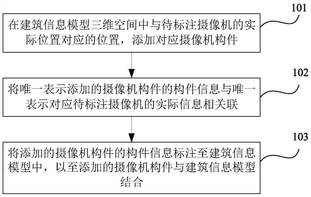
[0035] Such as figure 1 As shown, the BIM-based camera labeling method provided by the embodiment of the present invention mainly includes the following steps:

[0036] 101. Adding a corresponding camera component at the position corresponding to the actual position of the camera to be marked in the three-dimensional space of the building information model;

[0037] 102. Associating the component information uniquely representing the added camera component with the actual information uniquely representing the corresponding camera to be marked;

[0038] In one embodiment of the present invention, the camera component and the corresponding physical camera are associated to establish real-time communication, which provides a basis for invoking the video stream of the physical camera.

[0039] 103. Mark the component in...


PUM


Abstract

The invention discloses a camera labeling method based on BIM, and also discloses a corresponding camera labeling device. The method comprises the following steps: adding a corresponding camera component at a position corresponding to an actual position of a to-be-labeled camera in a three-dimensional space of a building information model; associating the component information uniquely representing the added camera component with the actual information uniquely representing the corresponding to-be-labeled camera; and labeling the component information of the added camera component into the building information model, so that the added camera component is combined with the building information model. The method is used in a comprehensive video monitoring system, camera annotation in the whole range from a two-dimensional plane to a three-dimensional space can be achieved, the camera deployment situation in a building is displayed in a more visual mode, and the method for visiting the camera more transparently with higher integration level is provided.

Description

technical field [0001] The invention relates to a BIM-based camera labeling method and a BIM-based camera labeling device, belonging to the technical field of video surveillance. Background technique [0002] In the prior art, the integrated video monitoring system usually selects a location on a GIS map to complete the labeling function. This is no problem for implementing annotations in a 2D plane. However, if it is in a building, the two-dimensional plane cannot accurately mark all the cameras inside the building. If the same longitude and latitude are used for labeling, the label data will overlap each other, or be hashed around after position offset, making it impossible to visually see the exact positions of these cameras. In the two-dimensional plane, the visualization of the marked points is poor. At the same time, when the network environment cannot access the Internet, there is a possibility that the online map cannot be loaded and the map cannot be displayed, an...

Claims


Application Information

Patent Timeline
IPC IPC(8): G06T19/20H04N7/18
Inventor 徐震南李明春单洪政李如辉丁晓强孙翔
Owner 佳讯飞鸿(北京)智能科技研究院有限公司
Why Eureka
Try Eureka