Intelligent wearable device with emergency alarm function
A smart wearable device, emergency alarm technology, applied in bracelets, watch straps, clothing, etc., can solve problems such as exposure of pulse detection equipment
- Summary
- Abstract
- Description
- Claims
- Application Information
AI Technical Summary
Problems solved by technology
Method used
Image
Examples
Embodiment 1
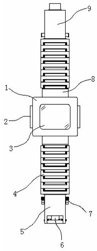
[0035] Example 1: See Figure 1-6 , a smart wearable device with an emergency alarm function, comprising a casing 1, a first strap 5, a hinge block 8 and a second strap 9, a storage structure 2 is arranged between two sides of one end inside the casing 1, and the casing The inside of the other end of the body 1 is fixedly connected with a display 3, and the top and bottom ends of the outer side of the housing 1 are respectively fixedly connected with a hinge block 8, and the bottom end of the hinge block 8 is provided with a first strap 5, and the top end of the hinge block 8 is provided with a There is a second watch strap 9, an elastic structure 4 is arranged between the first watch strap 5 and the second watch strap 9 and the hinge block 8 respectively, and a clip is provided between the top end of the first watch strap 5 and the bottom end of the second watch strap 9. A joint structure 6, fastening structures 7 are respectively provided on both sides between the first watc...
Embodiment 2
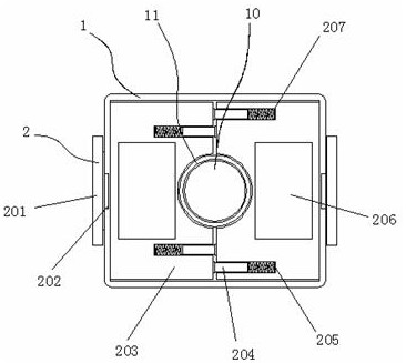
[0039] Embodiment 2: The storage structure 2 is composed of a pull rod 201, a groove 202, a storage box 203, a connecting rod 204, a return spring 205, a cavity 206 and a spring groove 207. The storage boxes 203 are respectively arranged on both sides of the housing 1, The interior of one end of the storage box 203 is provided with a cavity 206, one side of the storage box 203 passes through the housing 1 and is fixedly connected with a pull rod 201, the grooves 202 are respectively arranged on both sides of the outside of the housing 1, and the top of one side of the storage box 203 A spring groove 207 is respectively arranged at the bottom end, and a return spring 205 is fixedly connected to one side inside the spring groove 207, and a connecting rod 204 is fixedly connected between the return spring 205 and one side of the storage box 203;
[0040] Both the storage box 203 and the cavity 206 are distributed symmetrically about the longitudinal vertical midline of the casing ...
Embodiment 3
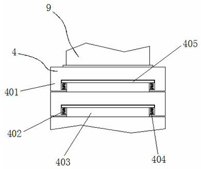
[0042] Embodiment 3: The elastic structure 4 is composed of a component 401, a movable groove 402, a sliding plate 403, an adjustment spring 404 and a cross bar 405. The component 401 is fixedly connected to one end of the first strap 5 and the second strap 9 respectively. The component 401 A movable groove 402 is arranged between the two sides inside the bottom end, and the bottom ends on both sides inside the movable groove 402 are fixedly connected with adjusting springs 404 respectively, and a cross bar 405 is fixedly connected between the tops of the adjusting spring 404, and the cross bar 405 A sliding piece 403 is fixedly connected between the bottom end of the assembly 401 and the top end;
[0043] The crossbar 405 is embedded in the movable groove 402, and the crossbar 405 and the movable groove 402 are on the same horizontal plane;
[0044] The adjustment springs 404 are respectively arranged at equal intervals with the two sides inside the movable groove 402;
[00...
PUM
 Abstract
Description
Claims
Application Information
 - R&D
- Intellectual Property
- Life Sciences
- Materials
- Tech Scout
- Unparalleled Data Quality
- Higher Quality Content
- 60% Fewer Hallucinations
Browse by: Latest US Patents, China's latest patents, Technical Efficacy Thesaurus, Application Domain, Technology Topic, Popular Technical Reports.
© 2025 PatSnap. All rights reserved.Legal|Privacy policy|Modern Slavery Act Transparency Statement|Sitemap|About US| Contact US: help@patsnap.com


