
A dust and hair cleaning device

A technology for cleaning devices and hair, which is applied to household cleaning devices, cleaning equipment, cleaning of boots and shoes, etc., can solve the problems of easy occurrence of odor, difficult to clean, poor internal hygiene, etc., and achieves reduced stress area and good cleaning effect. , Improve the effect of cleanliness

Active Publication Date: 2021-12-17
衡阳瑞源源实业发展有限公司
View PDF0 Cites 0 Cited by
  • Summary
  • Abstract
  • Description
  • Claims
  • Application Information

AI Technical Summary

Problems solved by technology

[0005] Aiming at the deficiencies in the prior art, the present invention provides a dust and hair cleaning device, which solves the problem that the existing indoor sole cleaning machine can only simply process the soles and remove part of the dust, but the cleaning effect is poor. Wet dust is not easy to clean, and after cleaning, the dust is easy to stick to the inner wall of the cleaning machine, resulting in poor internal sanitation and prone to peculiar smell, which has great limitations, and flexible linear objects such as hair and cotton thread are easy to Problems entangled in internal components

Method used


Image

  • A dust and hair cleaning device
  • A dust and hair cleaning device
  • A dust and hair cleaning device

Examples


Embodiment example 1

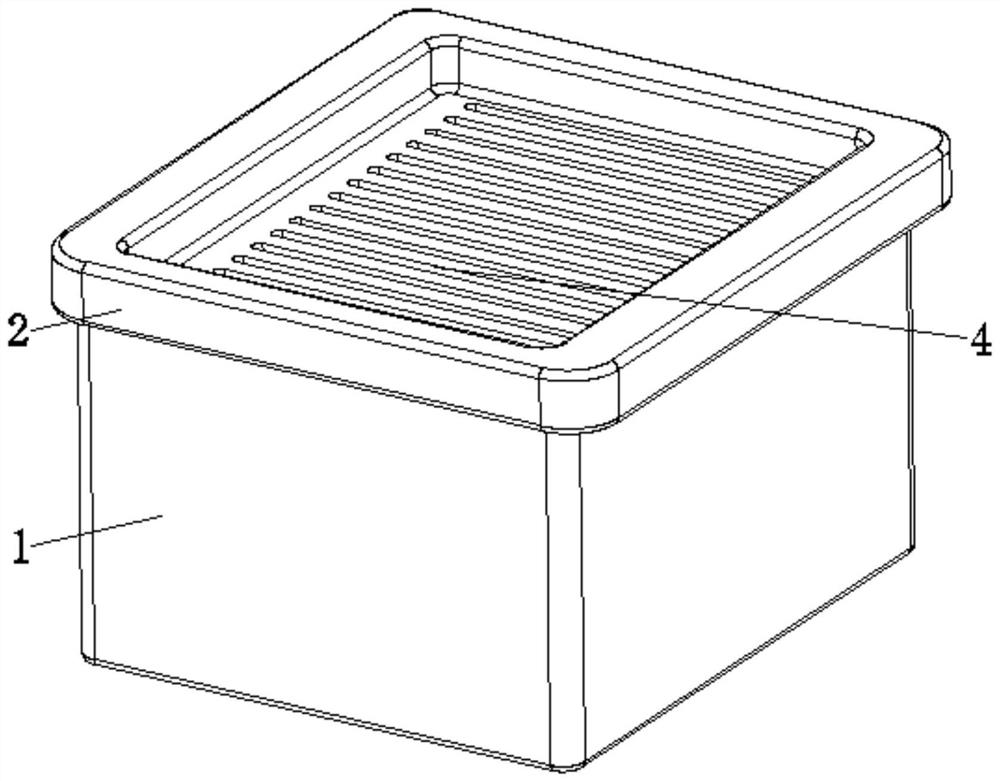
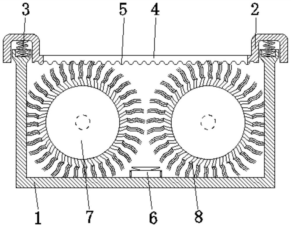
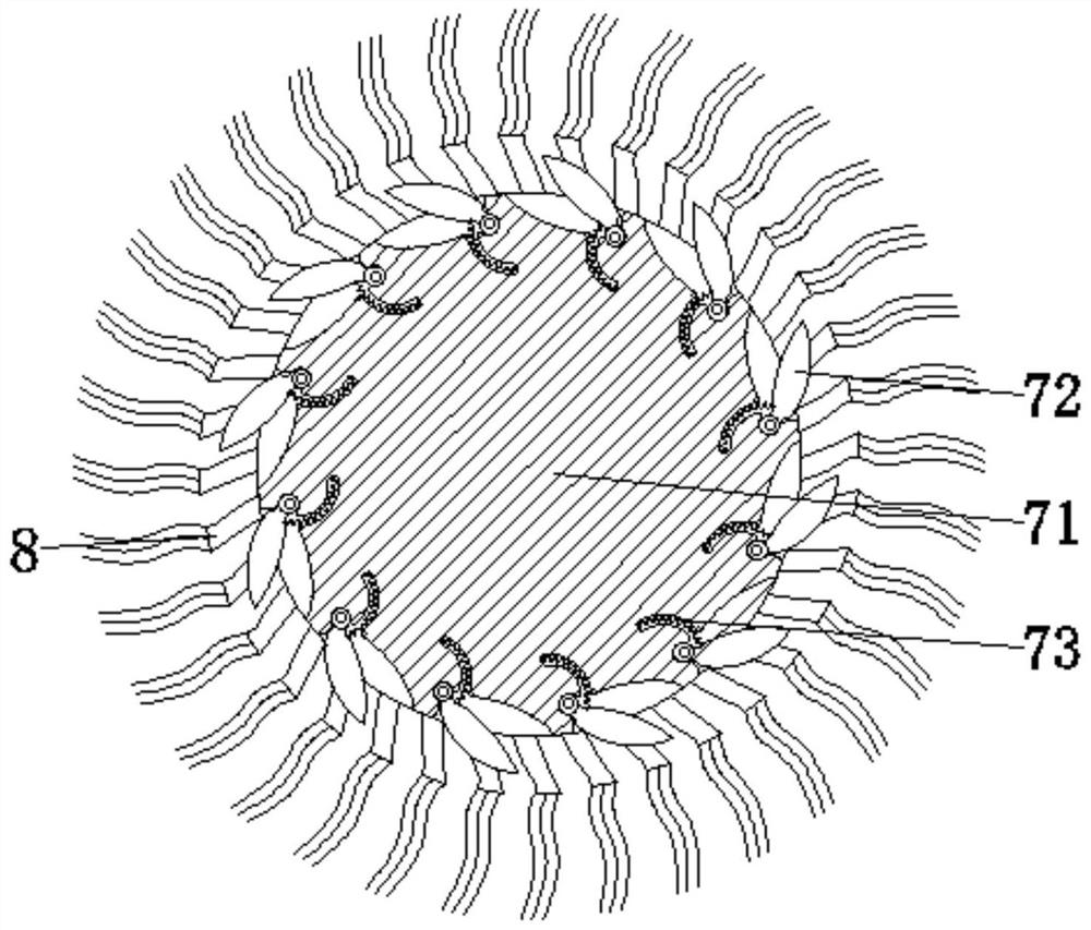
[0032] see Figure 1-7 , the present invention provides a technical solution: a dust and hair cleaning device, including a box body 1, a top cover 2, a support spring 3, a straight hole 4, and a wave pattern 5, and the top cover 2 is connected to the top of the box body 1, The support spring 3 is fixed between the top of the box body 1 and the top of the inner wall of the top cover 2. The inline hole 4 is set at the center of the surface of the top cover 2, and the wave pattern 5 is set at the bottom of the top cover 2 and is located at the bottom of the top cover 2. The position of the in-line hole 4, the inside of the box body 1 is equipped with a vacuum cleaner 6, a roller device 7, and a dust brushing device 8. The vacuum cleaner 6 is fixed at the bottom center of the inner wall of the box body 1, and the roller device 7 is rotatably connected to the inner wall of the box body 1. between the two sides of the vacuum cleaner 6, the dust brushing device 8 is fixed on the surf...

Embodiment example 2

[0036] The dust brushing device 8 is provided with a support rod 81, a side rod 82, an impact device 83, a return spring 84, and a hair brush 85. The side rod 82 is fixed on the two sides corresponding to the top of the support rod 81 surface, and the impact device 83 is slidably connected to the support rod. 81, the return spring 84 is fixed between the bottom of the impact device 83 and the inside of the support rod 81, and the brush 85 is fixed on the top of the support rod 81. Under the elastic force provided by the return spring 84, the impact device 83 The top of the roof is closely attached to the corrugated pattern 5, and when the rotating drive roller 71 rotates, the impact device 83 strikes the top of the inner wall of the top cover 2 back and forth, thereby generating vibrations, preventing wet dust from adhering to the inner wall, and the top cover 2 is Descending after being subjected to the gravity of the human body, the rotating driving roller 71 rotates, and the...


PUM


Abstract

The invention discloses a dust and hair cleaning device, which comprises a box body, a top cover, a support spring, a straight hole, and a wave pattern. Between the two sides corresponding to the top of the inner wall of the top cover, the in-line hole is opened at the center of the surface of the top cover, the wave pattern is opened at the bottom of the top cover and is located at the position of the in-line hole, and the vacuum cleaner is fixed At the center of the bottom of the inner wall of the box, the roller device is rotatably connected between the two sides corresponding to the inner wall of the box and is located on both sides of the vacuum cleaner. Correspondingly, the present invention relates to the technical field of daily necessities. The dust and hair cleaning device achieves the purpose of cleaning dust and hair, and can timely process flexible linear objects such as dust, hair, and cotton thread, and can quickly and thoroughly process dust, while reducing hair entanglement and improving use performance.

Description

technical field [0001] The invention relates to the technical field of daily necessities, in particular to a dust and hair cleaning device. Background technique [0002] With the continuous development of science and technology, society is also making continuous progress, and people's quality of life is also constantly improving. With the improvement of people's living standards, the decoration in houses, hotels and office buildings is more and more luxurious, and the cleanliness inside is also unprecedented. In order to maintain the sanitation inside, the frequency and intensity of cleaning should be reduced. After going out, it is inevitable that dust or flexible threads will be attached to the shoes, such as hair, cotton thread, etc. With the continuous improvement of people's material living standards, people's spiritual life is also constantly improving. It has become a fashion to pay attention to hygiene and protect the environment. Therefore, when people are in famil...

Claims


Application Information

Patent Timeline
Patent Type & Authority Patents(China)
IPC IPC(8): A47L23/22
Inventor 冷明宇
Owner 衡阳瑞源源实业发展有限公司
Learn More