
Hammering tool

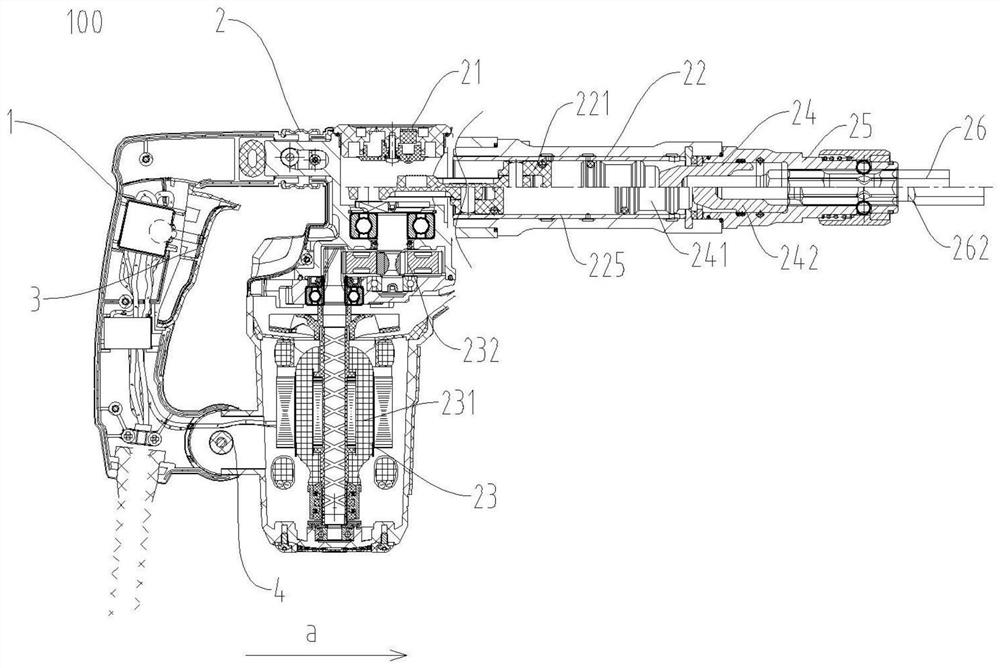
A tool and hammering technology, applied in the field of electric tools, can solve the problems of large vibration, secondary rework, and large impact force of hammering tools, and achieve the effect of protecting the chuck and reducing vibration

Pending Publication Date: 2021-04-20
POSITEC POWER TOOLS (SUZHOU) CO LTD
View PDF0 Cites 2 Cited by
  • Summary
  • Abstract
  • Description
  • Claims
  • Application Information

AI Technical Summary

Problems solved by technology

In this operation process, because the operator cannot continue to apply a constant thrust to the hammering tool, when the thrust is too large, the depth of wall peeling does not meet the engineering requirements and requires secondary rework; when the thrust is too small, the hammering tool will be damaged. Frequent switching between no-load state and load state
In the prior art, because the air pressure in the air chamber between the piston and the hammer in the hammering tool is too large, the impact force is relatively large, which will produce a reaction force on the flower hammer, so that the flower hammer hits the ram and the ram in the opposite direction. The hammer, lance and ram cannot stop the reciprocating motion, which causes problems such as large vibration of the hammering tool, poor operating feel, broken chuck parts and screws, etc.

Method used


Image

  • Hammering tool
  • Hammering tool
  • Hammering tool

Examples


Embodiment Construction

[0025] The technical solutions of the present invention will be clearly and completely described below in conjunction with the accompanying drawings. Apparently, the described embodiments are some of the embodiments of the present invention, but not all of them. Based on the embodiments of the present invention, all other embodiments obtained by persons of ordinary skill in the art without making creative efforts belong to the protection scope of the present invention.

[0026] In the description of the present invention, it should be noted that the terms "center", "upper", "lower", "left", "right", "vertical", "horizontal", "inner", "outer" etc. The indicated orientation or positional relationship is based on the orientation or positional relationship shown in the drawings, and is only for the convenience of describing the present invention and simplifying the description, rather than indicating or implying that the referred device or element must have a specific orientation, ...


PUM


Abstract

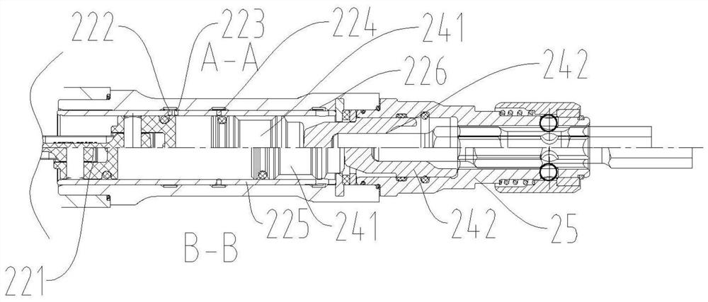
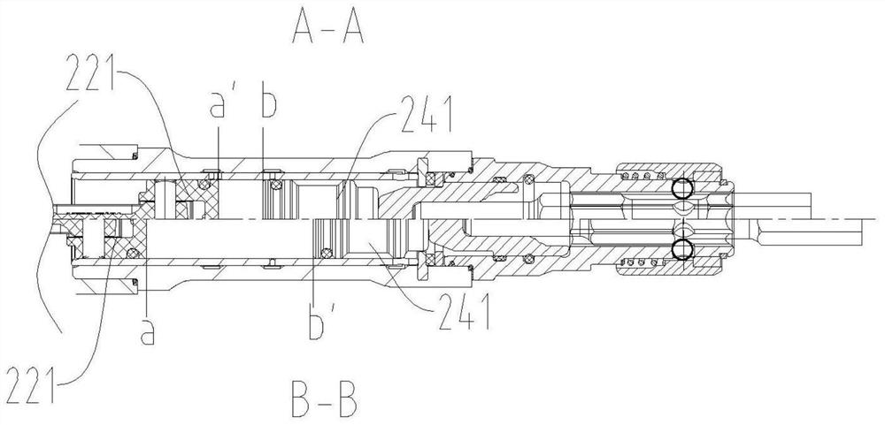
The invention relates to a hammering tool. The hammering tool comprises a shell, a chuck, an impact mechanism and a driving mechanism, wherein the chuck is arranged at the front end of the shell and is used for accommodating a working head; the impact mechanism comprises an air cylinder arranged in the shell, a piston accommodated in the air cylinder, a rammer matched with the piston and an impact rod capable of transmitting the impact force of the rammer to the working head; and the driving mechanism is accommodated in the shell and used for driving the piston to reciprocate between a first position far away from the chuck and a second position close to the chuck in the axial length direction of the air cylinder. An air chamber is formed between the piston and the rammer, and the rammer can reciprocate between an initial position and a tail end position under the driving force of the air chamber so as to drive the rammer to hammer the working head. A pressure adjusting air hole communicating with the inside and the outside of the air cylinder is formed in the side wall of the air cylinder, the pressure adjusting air hole is formed between the second position of the piston and the initial position of the rammer, when the rammer reciprocates between the initial position and the tail end position, at least part of air in the air chamber is exhausted out of the air cylinder through the pressure adjusting air hole, and the structure is simple, rapid and convenient.

Description

technical field [0001] The invention relates to a hammering tool, which belongs to the technical field of electric tools. Background technique [0002] In the construction industry in recent years, there is a requirement for the verticality accuracy between the ceiling and the wall. When the verticality does not meet the requirements, it is necessary to use a hammering tool such as an electric hammer or an electric pick to smooth the wall. The working head installed by the hammering tool is called a flower hammer. During the working process, the user needs to give the hammering tool a constant thrust so that the flower hammer can evenly peel off the concrete on the surface of the wall. In this operation process, because the operator cannot continue to apply a constant thrust to the hammering tool, when the thrust is too large, the depth of wall peeling does not meet the engineering requirements and requires secondary rework; when the thrust is too small, the hammering tool ...

Claims


Application Information

Patent Timeline
Patent Type & Authority Applications(China)
IPC IPC(8): B25D9/08B25D17/00
Inventor 孙井龙朱伯元毋宏兵
Owner POSITEC POWER TOOLS (SUZHOU) CO LTD
Learn More