
Shed tunnel structure capable of effectively resisting impact of falling stone

A technology of shed holes and rockfalls, applied in protective equipment, springs/shock absorbers, vibration suppression adjustment, etc., can solve the problem of shock absorbers being too late to deform and consume energy, and achieve the effect of simple and convenient replacement.

Active Publication Date: 2021-06-18
CHINA CONSTR EIGHT ENG DIV CORP LTD
View PDF17 Cites 2 Cited by
  • Summary
  • Abstract
  • Description
  • Claims
  • Application Information

AI Technical Summary

Problems solved by technology

However, the impact point is not the setting point of the shock absorber. This method does not change the essence of "head-to-head" at the impact point. The violent release of rockfall kinetic energy at the "fall point" will inevitably cause impact damage, which is intuitively manifested as the shock absorber at the support. It is too late to deform and consume energy, and the concrete at the collision point has already been smashed. Therefore, impact damage is still very common in applications.

Method used


Image

  • Shed tunnel structure capable of effectively resisting impact of falling stone
  • Shed tunnel structure capable of effectively resisting impact of falling stone
  • Shed tunnel structure capable of effectively resisting impact of falling stone

Examples


Embodiment 1

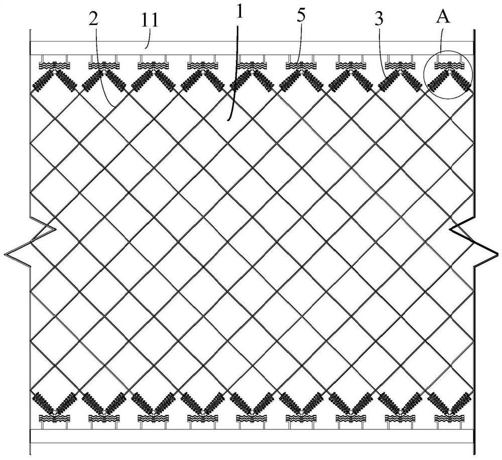
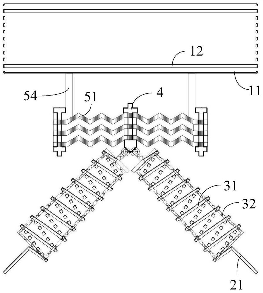
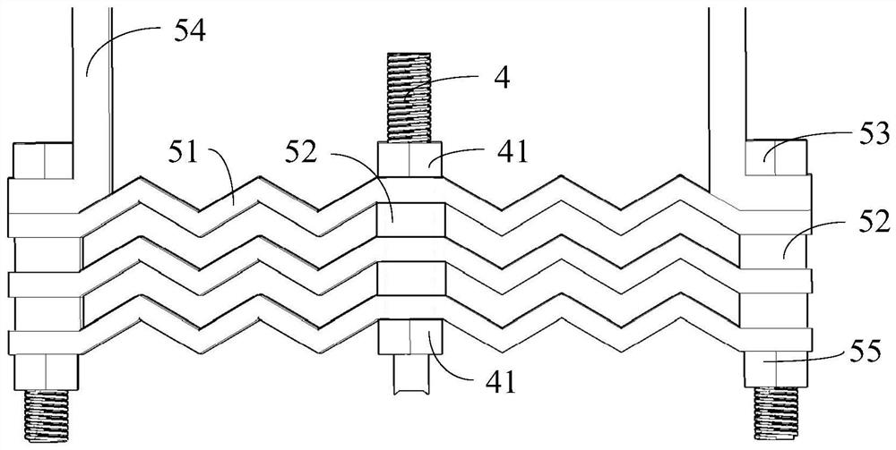
[0040] Such as figure 1 As shown, the shed cave structure effectively resisting the impact of falling rocks in the embodiment of the present invention includes a shed cave roof 1, a protective net 2, a plurality of elastic energy dissipation components 3 and a plurality of ductile energy dissipation components 5, wherein the shed cave roof 1 is Concrete slabs. Wherein the protective net 2 is arranged above the roof 1 of the shed cave at a certain interval, and the protective net 2 is formed by intersecting a plurality of hinge ropes 21; 31 provides a friction sleeve 32 that frictionally dissipates energy with the inner wall of the spring 31; the ductile energy-dissipating member 5 is detachably connected between the shed cave roof 1 and the elastic energy-dissipating component 3, and the ultimate tensile force of the ductile energy-dissipating member 5 is less than that of the elastic The ultimate tensile force of the energy dissipation component 3.

[0041] In this example,...

Embodiment 2

[0048] Compared with Example 1 Figure 1-8 and the second example Figure 1-4 , 6, 9-10, the difference between the second embodiment and the first embodiment lies in the connection assembly 6, combined with Figure 9-11 As shown, the connection assembly 6 includes a U-shaped plate 621 fixed at the end of the screw rod 4 and a connecting rod 622 hinged in the U-shaped plate 621 through a rotating shaft or a bolt and nut. One end of the connecting rod 622 passes through the through hole 34 and the friction sleeve 32 fixed connections, such as Figure 10 As shown, the opposite two side plates of the U-shaped plate 621 are respectively provided with perforations (non-threaded holes), and the connecting rod 622 of the friction sleeve 32 is also provided with perforations, and the bolts pass through the U-shaped plate 621 and the connecting rod 622. perforated and locked by nuts, wherein only one bolt is connected to each U-shaped plate 621 and connecting rod 622, so that the con...


PUM


Abstract

The invention discloses a shed tunnel structure capable of effectively resisting impact of falling rock. The shed tunnel structure comprises: a shed tunnel top plate, wherein a top plate frame is fixedly arranged on the peripheral side of the upper surface of the shed tunnel top plate; a protective net, which is arranged above the top plate of the shed tunnel at certain intervals and is formed by arranging a plurality of hinged ropes in a crossed mode; a plurality of elastic energy dissipation assemblies, wherein each elastic energy dissipation assembly comprises a spring fixedly connected to the rope end of the hinged rope and a friction sleeve arranged in the spring and used for friction energy dissipation with the inner wall of the spring; and a plurality of ductile energy consumption pieces, wherein the ultimate tensile strength of the ductile energy consumption pieces is smaller than the ultimate tensile strength of the springs, and the ductile energy consumption pieces are detachably arranged between and connected with the top plate frame and the elastic energy consumption assemblies. According to the invention, the falling stone collides with the protective net, so all the elastic energy dissipation assemblies are stretched to store energy, impact damage of a shed tunnel caused by concentrated release of kinetic energy of the falling stone at one part is avoided, energy is transmitted through soft contact, and strong impact force caused by hard collision is avoided.

Description

technical field [0001] The invention relates to the technical field of shed cave construction, in particular to a shed cave structure that can effectively resist the impact of falling rocks. Background technique [0002] When highways and railways pass through dangerous areas such as cut walls and canyons, they face serious threats from rolling rocks and falling rocks. As protective structures, shed tunnels play an extremely important role in the project. At present, the traditional "protective cushion shed hole (sand and gravel cushion layer is laid on the shed hole board)" and the new "energy dissipation and shock absorption shed hole (cylindrical shell ductile energy-dissipating parts are installed at the support)" are commonly used. Although the former has alleviated the impact load of falling rocks to a certain extent, it has not thoroughly removed the impact hazards of rolling stones and falling rocks, and all have their own fatal defects. [0003] For the protective ...

Claims


Application Information

Patent Timeline
Patent Type & Authority Applications(China)
IPC IPC(8): E01F7/04F16F15/067
CPCE01F7/045F16F15/067
Inventor 熊国军孙旻左建平韩磊袁青云方兴杰
Owner CHINA CONSTR EIGHT ENG DIV CORP LTD
Learn More