Construction method of movable assembled light formwork cast-in-place box culvert

A construction method and technology of cast-in-place box culverts, which are applied in the direction of buildings and road floors, etc., can solve problems such as difficulty in refitting, heavy hydraulic formwork trolley itself, and easy deformation of formwork

Inactive Publication Date: 2021-04-20
四川路航建设工程有限责任公司
View PDF10 Cites 0 Cited by
  • Summary
  • Abstract
  • Description
  • Claims
  • Application Information

AI Technical Summary

Problems solved by technology

The traditional box culvert construction method is to erect a full-scale bracket and cast in-situ concrete. The bracket erection and disassembly cycle is long, the construction efficiency is low, and the labor cost is high. This disadvantage is more obvious in projects with a large amount of box culvert.
At the same time, due to the easy deformation of the formwork, or the technical level of the workers and the quality of operation, the box culverts constructed by the traditional construction method are prone to poor concrete surface flatness and joint misalignment, and the appearance quality is not easy to be guaranteed.
[0003] With the advancement of engineering science and technology and the country's requirements for quality engineering construction, it is necessary to carry out technical innovations on traditional construction methods. For this reason, in recent years, people have applied hydraulic formwork trolley technology to box culvert construction, but hydraulic formwork trolleys also have their own cumbersomeness. Disadvantages such as easy transition, difficult modification, troublesome repair after damage, etc., the disadvantages are very obvious when the construction volume is small, scattered, or box culverts with various cross-sectional sizes, the formwork amortization cost is also high, and it is difficult to realize technology promotion

Method used


Image

  • Construction method of movable assembled light formwork cast-in-place box culvert
  • Construction method of movable assembled light formwork cast-in-place box culvert
  • Construction method of movable assembled light formwork cast-in-place box culvert

Examples


Embodiment Construction

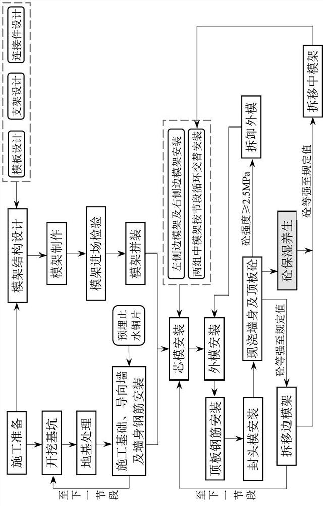
[0061] The following will be combined with Figure 1-Figure 15 The present invention is described in detail, and the technical solutions in the embodiments of the present invention are clearly and completely described. Apparently, the described embodiments are only some of the embodiments of the present invention, not all of them. Based on the embodiments of the present invention, all other embodiments obtained by persons of ordinary skill in the art without making creative efforts belong to the protection scope of the present invention.

[0062] The present invention provides a construction method for cast-in-place box culverts with movable assembled light-duty formwork through improvement; this construction method is applicable to the construction of cast-in-place reinforced concrete box culverts in highways, railways, water conservancy projects, and municipal pipe gallery projects.

[0063] The characteristics of the method are as follows:

[0064] (1) The movable assemble...


PUM


Abstract

The invention discloses a construction method of a movable assembled light formwork cast-in-place box culvert. The construction technological process is as follows; step 1, an assembled light formwork structure is designed and manufactured; step 2, formwork entry inspection and assembly are carried out; step 3, a box culvert foundation pit is excavated, and a foundation is treated; step 4, a construction bottom plate, a guide wall and wall body reinforcing steel bars are installed; step 5, a core mold and an outer mold are installed; step 6, roof reinforcing steel bars are installed; step 7, a plug plate is installed; step 8, the side wall and top plate concrete are poured and the concrete is cured; step 9, the outer mold is disassembled; step 10, the edge formwork is disassembled and moved; step 11, the middle formwork is disassembled and moved; and step 12, subsequent segment construction is conducted. The cast-in-place reinforced concrete box culvert is suitable for cast-in-place reinforced concrete box culvert construction in highway, railway, water conservancy and municipal pipe gallery projects.

Description

technical field [0001] The invention relates to the field of box culvert construction, in particular to a construction method for a cast-in-place box culvert of a movable assembled light formwork frame. Background technique [0002] Box culvert is a closed reinforced concrete thin-walled structure, which has the advantages of simple structure, convenient construction, good integrity, high rigidity, good durability, and low maintenance cost. It is often used in railway, highway and municipal road projects. In water conservancy It is more widely used in engineering and municipal pipe gallery projects. The traditional construction method of box culverts is to erect cast-in-place concrete with vertical formwork for full-wall brackets. The period of erecting and dismantling the brackets is long, the construction efficiency is low, and the labor cost is high. This disadvantage is more obvious in projects with a large amount of box culverts. At the same time, due to the easy defor...

Claims


Application Information

Patent Timeline
Patent Type & Authority Applications(China)
IPC IPC(8): E01F5/00
Inventor 胡明亮张剑宁汪琪唐强蒋华斌张凯陶永建熊丽蓓王朔蒋露宋平
Owner 四川路航建设工程有限责任公司
Why Eureka
Try Eureka