Flatness detection device for constructional engineering

A detection device and construction engineering technology, which is applied in the direction of electromagnetic measuring device, electric/magnetic roughness/irregularity measurement, etc., can solve the problems of low intelligence, inability to obtain level deviation value, inconvenient use, etc.

Pending Publication Date: 2021-04-20
LOUDI CITY WANBAO NEW DISTRICT DEV INVESTMENT CO LTD
View PDF0 Cites 6 Cited by
  • Summary
  • Abstract
  • Description
  • Claims
  • Application Information

AI Technical Summary

Problems solved by technology

[0003] Existing a kind of flatness detection device for construction engineering has the following disadvantages: 1. Most of the existing flatness detection device for construction engineering uses a level for detection, but the level is only suitable for the detection of shorter ground, not It is suitable for the flatness detection of long ground, which is not practical; 2. In the existing flatness detection device for construction engineering, both the spirit level and the spirit level adopt the liquid level principle of the vial, but this detection method First of all, it is impossible to obtain the specific level deviation value. Secondly, when reading the data in this way, people need to directly observe, and there are errors; 3. Most of the existing flatness detection devices for construction projects have no fixed structure and cannot be elongated. , that is, it is impossible to detect the ground at a long distance, which is not practical; 4. The existing flatness detection device for construction engineering has a low degree of intelligence and is inconvenient to use

Method used


Image

  • Flatness detection device for constructional engineering
  • Flatness detection device for constructional engineering
  • Flatness detection device for constructional engineering

Examples


Embodiment Construction

[0028] In order to make the technical means, creative features, goals and effects achieved by the present invention easy to understand, the present invention will be further described below in conjunction with specific embodiments.

[0029] In the description of the present invention, it should be noted that the terms "upper", "lower", "inner", "outer", "front end", "rear end", "both ends", "one end", "another end" The orientation or positional relationship indicated by etc. is based on the orientation or positional relationship shown in the drawings, and is only for the convenience of describing the present invention and simplifying the description, rather than indicating or implying that the referred device or element must have a specific orientation, use a specific Azimuth configuration and operation, therefore, should not be construed as limiting the invention. In addition, the terms "first" and "second" are used for descriptive purposes only, and should not be understood ...


PUM


Abstract

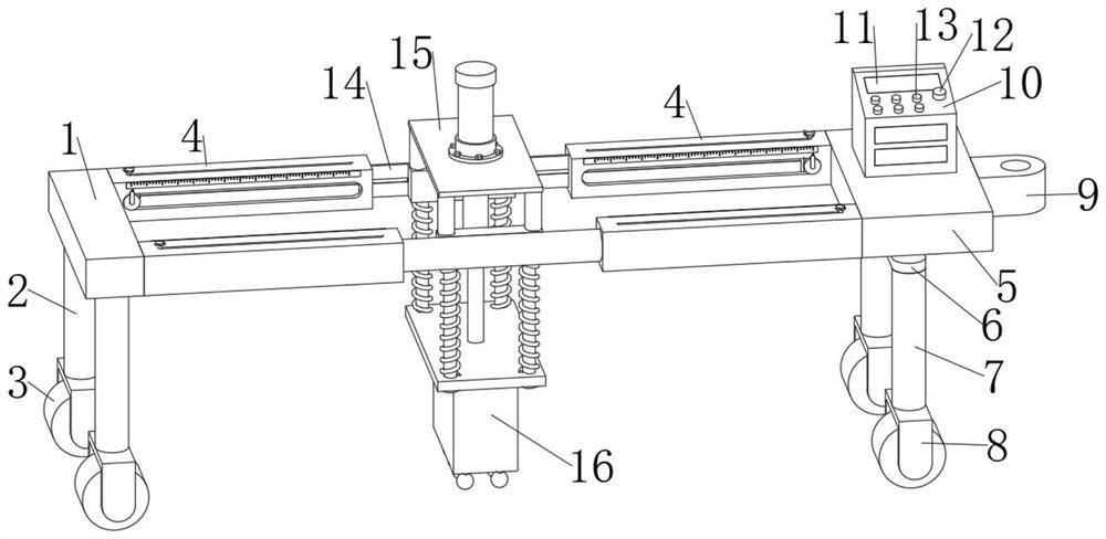
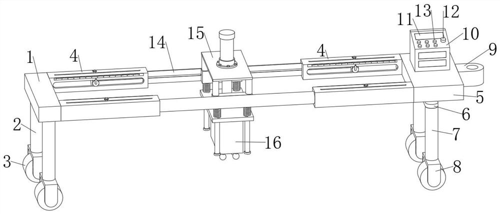
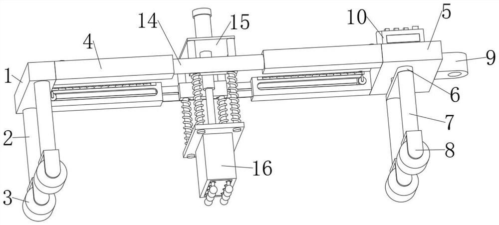
The invention discloses a flatness detection device for constructional engineering. The device comprises a left installation plate and a right installation plate, two first supporting columns which are symmetrical front and back are fixedly installed at the lower end of the left installation plate, first rolling wheels are fixedly installed at the lower ends of the two first supporting columns, and the right installation plate is located on the right side of the left installation plate; the lower end of the right installation plate is movably connected with a connecting plate through a bearing, two second supporting columns which are symmetrical front and back are fixedly mounted at the lower end of the connecting plate, second rolling wheels are fixedly mounted at the lower ends of the two second supporting columns, the second rolling wheels and the first rolling wheels are located on the same horizontal plane, and a traction ring is fixedly mounted at the right end of the right installation plate; and a console is fixedly mounted at the upper end of the right installation plate. According to the flatness detection device for constructional engineering, flatness detection can be conducted on the long-distance ground, a specific flatness deviation value can be obtained, the detection precision is high, the intelligent degree is high, operation is easy, use is convenient, and practicability is high.

Description

technical field [0001] The invention relates to the technical field of construction engineering detection, in particular to a flatness detection device for construction engineering. Background technique [0002] Construction engineering refers to the planning, survey, design and construction, completion and other technical work and the completed engineering entity and the installation project of the supporting lines, pipelines and equipment for new construction, reconstruction or expansion of houses, buildings and auxiliary structures and facilities. . It also refers to the construction of various houses and buildings, also known as construction workload. This part of the investment must be built and used, and can only be realized through construction activities. The flatness detection for construction engineering is mainly to detect the flatness of the ground. [0003] Existing a kind of flatness detection device for construction engineering has the following disadvantag...

Claims


Application Information

Patent Timeline
Patent Type & Authority Applications(China)
IPC IPC(8): G01B7/34
Inventor 王意曾振杰张敏敏刘颖畅杨亮军王慧斌苏嗣奎邬希丁刘志皇李刚周晶晶周志林
Owner LOUDI CITY WANBAO NEW DISTRICT DEV INVESTMENT CO LTD
Why Eureka
Try Eureka