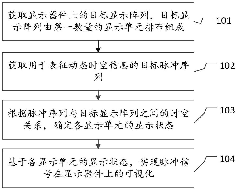
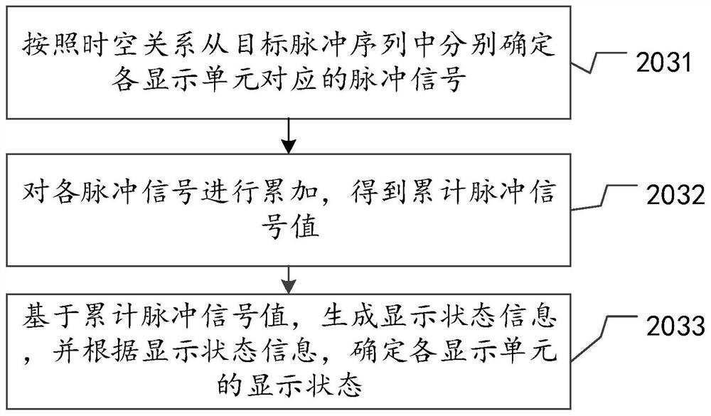
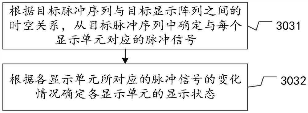
Display method, device, electronic equipment and medium based on pulse signal
A technology of pulse signal and display method, which is applied in the field of data processing and can solve the problems of loss of information and inability to accurately reproduce the change process of optical signals.
- Summary
- Abstract
- Description
- Claims
- Application Information
AI Technical Summary
Problems solved by technology
Method used
Image
Examples
Embodiment 1
[0141] by Figure 4 As shown, the generation rate V1 of the target pulse sequence is the same as the display rate V2 of the target display array, and the generation resolution R1 of the two is the same as the display resolution R2, and the light-emitting state signal includes on and off:
[0142] Based on the ratio of the generation rate V1 to the display rate V2 being 1, and the ratio of the generation resolution R1 to the display resolution R2 being 1, the temporal-spatial relationship is determined as:
[0143] The target display array corresponds to a pulse plane corresponding to the input target pulse sequence, and each display unit corresponds to a pulse signal of a pulse position on the pulse plane. The display unit is, for example, a pixel unit.
[0144] The threshold value is 1, the pulse signal is 1, the cumulative pulse signal value is 1, the display status information is on, and the corresponding display unit is controlled to light up; the pulse signal is 0, the c...
Embodiment 2
[0146] by Figure 5 As shown, the generation rate V1 of the target pulse sequence is the same as the display rate V2 of the target display array, both are 6*6 (that is, W=H=6), and the generation rate V1 of the target pulse sequence=40000 frames / second, the target display Array display rate V2 = 8000 frames per second:
[0147] For the pulse signal during 5 / 40000 seconds, according to the input order, it is expressed as follows (the first input pulse signal is first, and the second input pulse signal is last): the above target pulse sequence is according to the resolution 6*6 and the input order, the above target pulse The sequence corresponds to 5 pulse planes (pulse frames), for example Image 6 As shown, based on the same resolution, each display unit corresponds to a pulse position in the pulse plane in space; based on V1 / V2=5, then in time, each display unit corresponds to the pulse in 5 pulse planes Position pulse signal. The five pulse signals are accumulated, and di...
Embodiment 3
[0150] by Figure 7 As shown, the generation resolution R1 of the input target pulse sequence is 6*6, and the display resolution R2 of the target display array is 2*2; the generation rate of the target pulse sequence V1=40000 frames / second, and the display rate of the target display array is V2=8000 frames / second; display status information including voltage value:
[0151]The received target pulse sequence is the same as that in Embodiment 2. And based on resolution R1 / R2=9, each display unit corresponds to 9 pulse positions in the pulse plane; based on V1 / V2=5, each display unit corresponds to pulse signals in 5 pulse planes. At this time, the 9 pulse positions of the 5 pulse planes are accumulated, and the weighted accumulation method is adopted. The pulse signals of different pulse positions have different weights, and the weight matrix is:
[0152] 1 2 1 2 4 2 1 2 1
[0153] .
[0154] For the display units at positions (1, 1) and (1, 2), th...
PUM
 Abstract
Description
Claims
Application Information
 - R&D
- Intellectual Property
- Life Sciences
- Materials
- Tech Scout
- Unparalleled Data Quality
- Higher Quality Content
- 60% Fewer Hallucinations
Browse by: Latest US Patents, China's latest patents, Technical Efficacy Thesaurus, Application Domain, Technology Topic, Popular Technical Reports.
© 2025 PatSnap. All rights reserved.Legal|Privacy policy|Modern Slavery Act Transparency Statement|Sitemap|About US| Contact US: help@patsnap.com


