Eureka AIR delivers breakthrough ideas for toughest innovation challenges, trusted by R&D personnel around the world.

Vaginal splint for pelvic floor supporting

A vaginal and pelvic floor technology, applied in non-surgical orthopaedic surgery and other directions, can solve the problems of reducing the treatment effect, increasing the cost of mold opening and production and processing, and increasing the number of instruments to be prepared, so as to improve the treatment effect, ensure the integrity, Wide range of effects

Inactive Publication Date: 2021-04-23
蒋春
View PDF1 Cites 0 Cited by
  • Summary
  • Abstract
  • Description
  • Claims
  • Application Information

AI Technical Summary

Problems solved by technology

[0003] However, there are still relatively obvious defects in its use: 1. The width of the above-mentioned vaginal splints is not adjustable. If vaginal splints of various specifications are preset, it will not only increase the cost of mold opening and manufacturing and production and processing, but also increase the cost of instruments. The quantity prepared, and the various specifications also change in gradients, which cannot achieve stepless coverage, and cannot be applied to different physiological structures of different patients. It is easy to cause clamping instability due to too narrow splint, or too wide splint to cause 2. The vaginal splint needs to position the repair material on the exposed fascia, so the vaginal splint is usually set outwardly. During the removal of the vaginal splint, it is close to the repair material and the The fascia is easy to pull the original fixed repair material, thereby reducing the treatment effect

Method used


Image

  • Vaginal splint for pelvic floor supporting
  • Vaginal splint for pelvic floor supporting
  • Vaginal splint for pelvic floor supporting

Examples


Embodiment

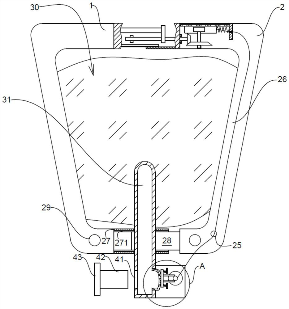
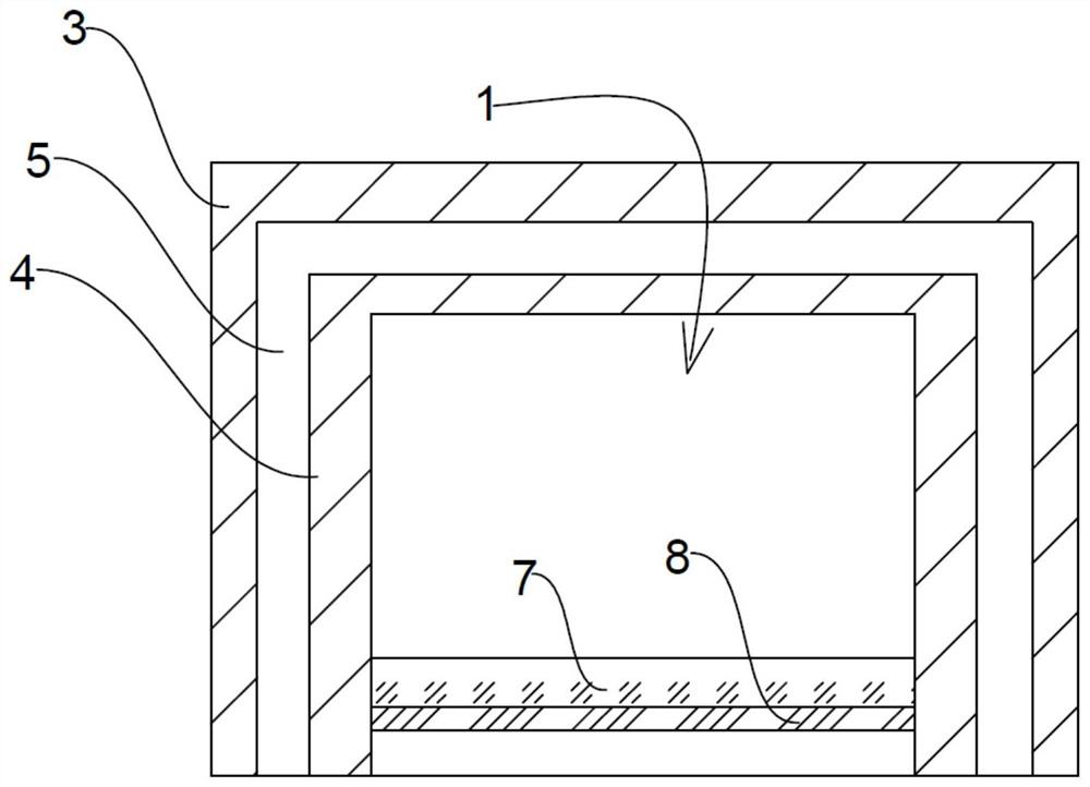
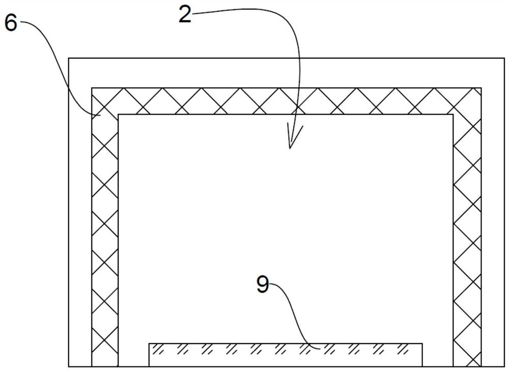
[0030] see Figure 1 to Figure 5 , the present invention provides a technical solution:

[0031] A vaginal splint for pelvic floor support, including a first support 1 and a second support 2, the first support 1 and the second support 2 are made of semi-rigid materials and have certain deformability, the first One side of a support 1 close to the second support 2 is fixedly provided with an outer inverted U-shaped plate 3 and an inner inverted U-shaped plate 4, and an inverted U-shaped groove is formed between the outer inverted U-shaped plate 3 and the inner inverted U-shaped plate 4 5. The side of the second support 2 close to the first support 1 is fixed with a middle inverted U-shaped plate 6, which can be inserted into the inverted U-shaped groove 5, and the middle inverted U-shaped plate 6 can be Moving in the inverted U-shaped groove 5, it will not break away from the inverted U-shaped groove 5 within the range of the minimum and maximum moving distances. The side of t...


PUM


Abstract

The invention provides a vaginal splint for pelvic floor supporting. The vaginal splint comprises a first supporting piece and a second supporting piece, wherein a lead screw is movably arranged on the side wall of an inner cavity of the second supporting piece in a penetrating mode, and an adjusting gear is arranged on a rack in an engaged mode; an expandable member is arranged on the opposite surfaces of the first supporting piece and the second supporting piece in an adhesive mode, an expandable bag is connected to an opening in one side of a communicating pipe, a pull wire sequentially penetrates through an open groove and a wire penetrating hole and then is wound around a rope winding column, and elastic protrusions are arranged on the sides, close to the rope winding column, of two clamping rods. According to the vaginal splint for pelvic floor supporting, the distance between the first supporting piece and the second supporting piece can be adjusted, the pull wire used for adjusting the distance can be automatically fixed and clamped when the expandable member is inflated, the pull wire can be automatically unlocked after deflation, and the vaginal splint can be used for pelvic floor supporting. The distance between the first supporting piece and the second supporting piece is reduced, taking out is convenient, and using is more convenient.

Description

technical field [0001] The invention relates to the technical field of pelvic floor support, in particular to a vagina splint for pelvic floor support. Background technique [0002] In the prior art, the application number is "CN200680039757.5", an adjustable vaginal splint for pelvic floor support, one embodiment of the vaginal splint assembly includes: a base portion with a connecting portion and first and second sides , the first and second sides extend outwardly from the first and second ends of the connecting portion to the first and second free ends, respectively. Also comprising a plurality of tip portions, each of the plurality of tip portions having a different size, and each having a connecting portion and first and second sides extending from the first and second sides of the connecting portion. and second ends extending outwardly toward first and second free ends, respectively, and at least first and second connecting members capable of securing the first free e...

Claims


Application Information

Patent Timeline
IPC IPC(8): A61F5/00
CPCA61F5/00
Inventor 蒋春
Owner 蒋春
Why Eureka
Eureka Blog
Learn More