
A novel magneto-rheological damper and damping control method for vehicle suspension system

A magnetorheological damper and rear damper technology, applied in suspension, elastic suspension, vehicle parts, etc., can solve the problems of few switching characteristics, poor performance, general damping control effect in high-speed piston area, etc. Achieve the effect of improving ride comfort, handling, and damping coefficient

Active Publication Date: 2021-09-24
WUHAN UNIV OF TECH
View PDF6 Cites 0 Cited by
  • Summary
  • Abstract
  • Description
  • Claims
  • Application Information

AI Technical Summary

Problems solved by technology

However, the rheological properties of magnetorheological fluid are mainly used in the design of magnetorheological shock absorbers at present, and there are very few applications for its switching characteristics.
[0003] Most of the existing magneto-rheological dampers are designed for the center of gravity of the car caused by the engine, but when the position of the center of gravity of the car changes, the performance will deteriorate
Moreover, the existing design can only adjust the damping coefficient of the shock absorber in the low-speed area of ​​the piston, and the control effect on the sudden change point of the damping coefficient of the magneto-rheological shock absorber and the damping control in the high-speed area of ​​the piston is general.
In addition, in terms of magneto-rheological damper optimization and suspension matching, it is mostly designed for specific working conditions, without fully considering the distribution of the vehicle's center of gravity (such as the impact of carrying passengers, the impact of trunk cargo, etc.) and the vehicle's different working conditions. Influence of Lower Damper Characteristics on Suspension and Performance

Method used


Image

  • A novel magneto-rheological damper and damping control method for vehicle suspension system
  • A novel magneto-rheological damper and damping control method for vehicle suspension system
  • A novel magneto-rheological damper and damping control method for vehicle suspension system

Examples


Embodiment Construction

[0031] The following will clearly and completely describe the technical solutions in the embodiments of the present invention with reference to the drawings in the embodiments of the present invention.

[0032]In describing the present invention, it should be understood that the terms "center", "longitudinal", "transverse", "upper", "lower", "front", "rear", "left", "right", " The orientations or positional relationships indicated by "vertical", "horizontal", "top", "bottom", "inner" and "outer" are based on the orientations or positional relationships shown in the drawings, and are only for the convenience of describing the present invention and Simplified descriptions, rather than indicating or implying that the device or element referred to must have a particular orientation, be constructed and operate in a particular orientation, and thus should not be construed as limiting the invention. In addition, the terms "first", "second", etc. are used for descriptive purposes only...


PUM


Abstract

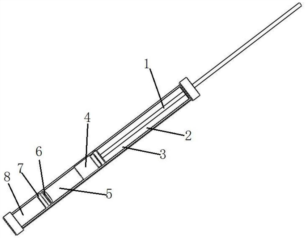
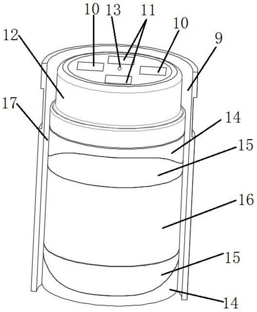
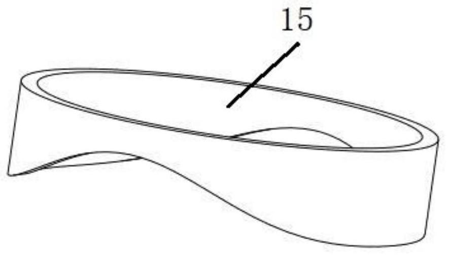
The invention discloses a novel magneto-rheological damper and a damping control method for a vehicle suspension system. The piston inner core has a main channel between the piston inner core and the piston shell. The piston inner core includes a main channel structure and a bypass channel structure. The main channel structure includes a first magnetic core, a first excitation coil, a sinusoidal magnetic pole and a sinusoidal magnetic barrier. Ring, the bypass channel structure is set on the top of the first magnetic core, the bypass channel structure includes the second magnetic core, the second excitation coil and the bypass hole, the piston rod is set on the top of the piston head, the magnetorheological fluid is set in the piston barrel, and the sinusoidal The magnetic poles control the flow cross-sectional area of ​​the main channel, and then control the damping coefficient of the damper, and the position of the abrupt change point of the slope of the damper is controlled by the switching action of the bypass hole attached to the piston head.

Description

technical field [0001] The invention relates to the technical field of automobile NVH, in particular to a novel magnetorheological damper and a damping control method for a vehicle suspension system. Background technique [0002] With the rapid development of automobiles, people have higher and higher requirements for the ride comfort of automobiles. The performance of automobile shock absorbers has an important impact on vehicle ride comfort and handling stability. Automotive shock absorbers are divided into passive shock absorbers, active shock absorbers and semi-active shock absorbers. Since the performance parameters of passive shock absorbers cannot be adjusted, high-quality ride comfort cannot be achieved under different working conditions. Active suspension can provide external force through the actuator to improve the ride comfort and handling stability of the vehicle, but it is expensive, requires additional energy input, and has high requirements for the controlle...

Claims


Application Information

Patent Timeline
Patent Type & Authority Patents(China)
IPC IPC(8): F16F9/53B60G17/0165B60G17/08
CPCB60G17/0165B60G17/08F16F9/535F16F2224/045
Inventor 刘志恩宋伟志卢炽华李永超安宏杰朱亚伟谢丽萍周辉
Owner WUHAN UNIV OF TECH
Learn More