A passive flameproof device with low wind resistance and implicit dust explosion

A dust explosion and implicit technology, applied to valve devices, devices to prevent accidental or unauthorized actions, engine components, etc., can solve the failure of explosion-proof, increase the economic cost of enterprises, and the difficulty of closing the flame-proof flap, etc. problems, to achieve the effect of preventing transmission

Active Publication Date: 2022-08-09
GUANGZHOU SPECIAL MECHANICAL & ELECTRICAL EQUIP INSPECTION & RES INST
View PDF7 Cites 0 Cited by
  • Summary
  • Abstract
  • Description
  • Claims
  • Application Information

AI Technical Summary

Problems solved by technology

At present, most companies involved in the potential risk of combustible powder explosions use passive flameproof devices, but traditional passive flameproof devices have obvious shortcomings: on the one hand, because the flameproof flap is a whole near-circular Due to the limitation of conditions, it cannot be opened at a large angle, and the wind resistance is large, which increases the additional operating economic cost of the enterprise. On the other hand, the traditional flameproof flap valve uses an external counterweight to assist the flameproof flap valve to open. At this time, due to the relatively long rotation moment of the counterweight around the rotation axis and the large mass of the counterweight, the closing process of the flameproof flap valve requires more work from the outside, especially the inertia effect of the counterweight, so that the flameproof flap can be closed in time and completely. It is difficult to close. Moreover, the closure of the traditional flameproof flap valve only depends on the impact of the leading shock wave of the dust explosion. Due to the short distance between the leading shock wave and the chemical reaction front, the traditional flameproof flap valve cannot be closed in a very short time. Complete closure in time, flameproof failure

Method used


Image

  • A passive flameproof device with low wind resistance and implicit dust explosion
  • A passive flameproof device with low wind resistance and implicit dust explosion
  • A passive flameproof device with low wind resistance and implicit dust explosion

Examples


Embodiment Construction

[0023] This part will describe the specific embodiments of the present invention in detail, and the preferred embodiments of the present invention are shown in the accompanying drawings. Each technical feature and overall technical solution of the invention should not be construed as limiting the protection scope of the invention.

[0024] In the description of the present invention, it should be understood that the azimuth description, such as the azimuth or position relationship indicated by up, down, front, rear, left, right, etc., is based on the azimuth or position relationship shown in the drawings, only In order to facilitate the description of the present invention and simplify the description, it is not indicated or implied that the indicated device or element must have a particular orientation, be constructed and operated in a particular orientation, and therefore should not be construed as limiting the present invention.

[0025] In the description of the present in...


PUM


Abstract

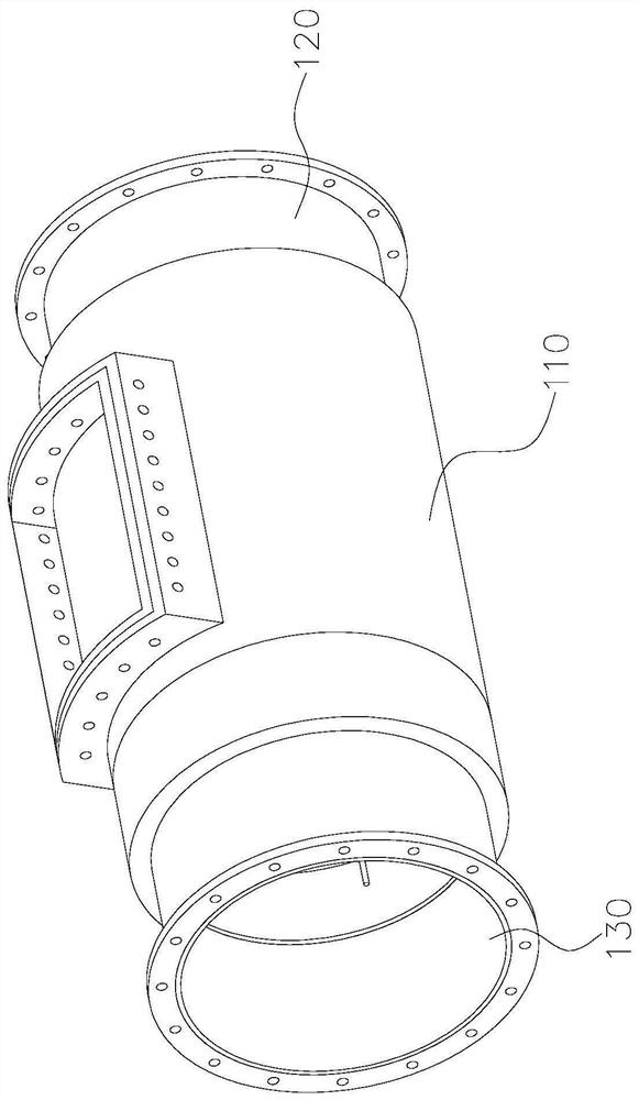
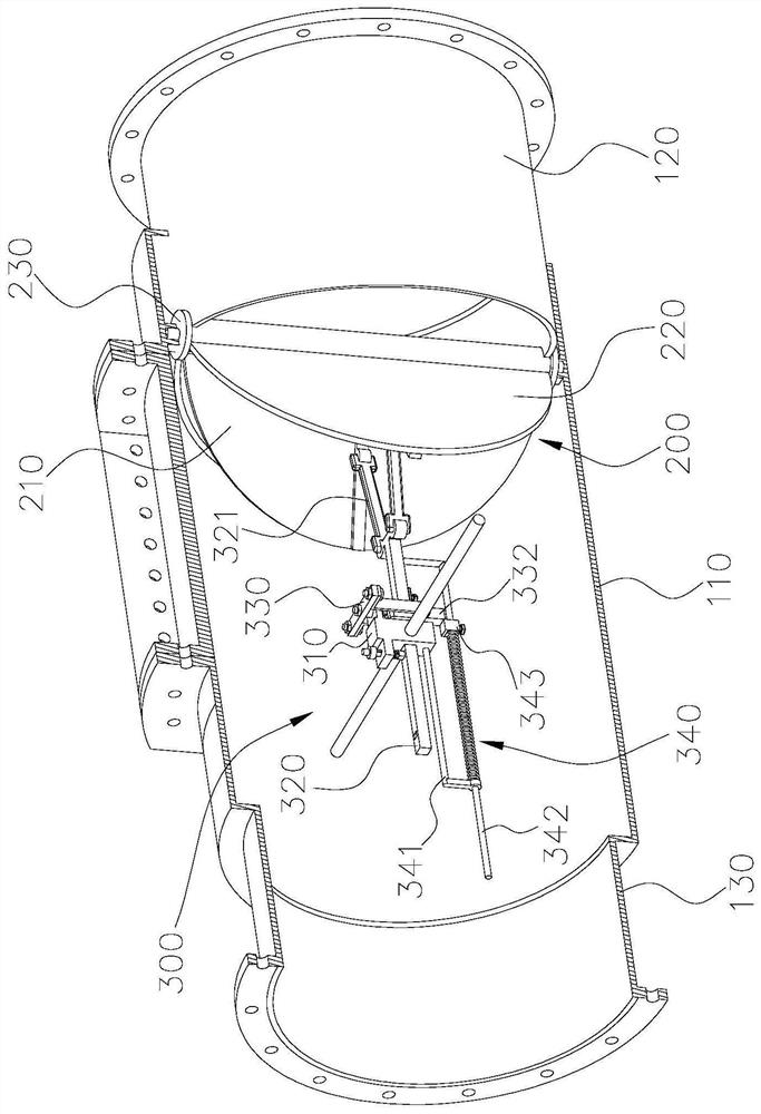
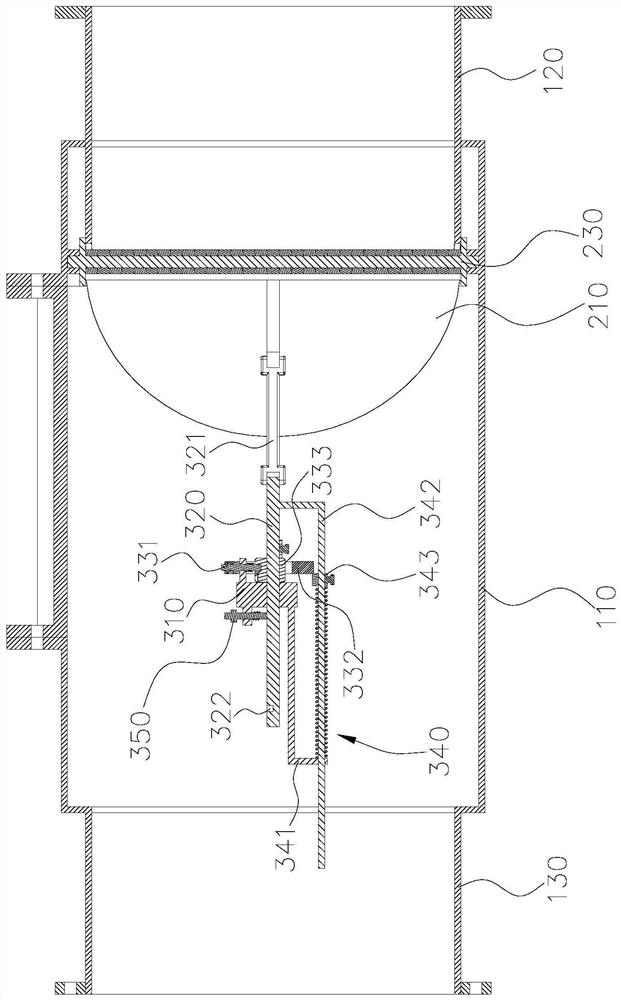
The invention discloses a passive flameproof device with low wind resistance and hidden dust explosion, which comprises a casing, two ends of the casing are respectively provided with a first pipe end and a second pipe end; In the housing; and the power assist mechanism, including a fixing piece, a sliding rod, a limit component and a boosting component, the fixing piece is fixed in the housing, the sliding rod and the fixing piece form a sliding pair, the sliding rod is connected to the explosion-proof flap, and the limit component and the booster The components are connected with fixed parts. The booster component includes a guide rod connected to the sliding rod. The limit component is used to limit the movement of the sliding rod and the guide rod. The limit component moves so that the sliding rod is coupled with the explosion shock wave under the action of the booster component. The flameproof flap closes the first pipe end. The invention relates to the technical field of dust explosion explosion protection. When dust explosion occurs, the device can effectively improve the closing speed of the explosion protection flap on the basis of maintaining the stability of passive action execution, and can realize complete isolation of the dust explosion propagation process.

Description

technical field [0001] The invention relates to the technical field of dust explosion explosion protection, in particular to a low wind resistance implicit dust explosion passive explosion protection device. Background technique [0002] Dust explosion flameproof device is used for isolation of dust explosion propagation process. At present, most companies involved in the potential risk of combustible powder explosion use passive flameproof devices, but the traditional passive flameproof devices have obvious shortcomings: Due to the limitation of conditions, it cannot be opened at a large angle, and the wind resistance is large, which increases the additional economic cost of operation of the enterprise. On the other hand, the traditional explosion-proof flap valve uses an external counterweight to assist the explosion-proof flap valve to open. Due to the long rotation moment of the counterweight around the rotating shaft and the large mass of the counterweight, the closing...

Claims


Application Information

Patent Timeline
Patent Type & Authority Patents(China)
IPC IPC(8): F16K17/36F16K35/10
CPCF16K17/363F16K35/10Y02E30/30
Inventor 丁建旭王继业王新华陈钰方王彦杨娟
Owner GUANGZHOU SPECIAL MECHANICAL & ELECTRICAL EQUIP INSPECTION & RES INST
Why Eureka
Try Eureka