Metalized film capacitor tray locking mechanism
A technology of metallized film and locking mechanism, applied in capacitors, capacitor manufacturing, circuits, etc., can solve the problem of time-consuming disassembly and replacement of trays
- Summary
- Abstract
- Description
- Claims
- Application Information
AI Technical Summary
Problems solved by technology
Method used
Image
Examples
Embodiment 1
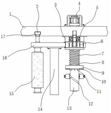
[0035] Example 1: See Figure 1-6 , a metallized film capacitor tray locking mechanism, comprising a main board 1, a base 3, a turntable 6 and a rod body 13, one side of the bottom end of the main board 1 is fixedly connected with a base 3, and the bottom end of the base 3 is movably connected with a turntable 6, the base One end between 3 and the turntable 6 is provided with a fixed structure 5, one side of the turntable 6 is fixedly connected with a connection plate 16, and a cleaning structure 14 is arranged at the middle position of the bottom end of the connection plate 16, and one side of the bottom end of the connection plate 16 is movable. The roller 15 is connected, one side of the top of the connecting plate 16 is fixedly connected with the insertion rod 2, the other side of the bottom of the main board 1 is provided with a limit groove 17, the inside of the base 3 is movably connected with a rod body 13, and the inside of the rod body 13 is provided with a lubricatin...
Embodiment 2
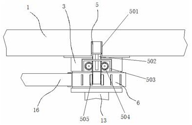
[0038] Embodiment 2: The fixed structure 5 is composed of a storage slot 501, a rack bar 502, a housing 503, a gear 504 and a block 505. The housing 503 is fixedly connected to the top of the base 3, and the two sides inside the housing 503 are respectively flexibly connected. There is a gear 504, a rack bar 502 is provided in the middle of the housing 503, a storage slot 501 is provided on one side of the bottom end of the main board 1, and blocks 505 are respectively fixedly connected to the top of the turntable 6
[0039] The gear 504 is distributed symmetrically about the vertical midline of the rack bar 502;
[0040] Specifically, such as figure 1 with figure 2 As shown, pull the roller 15 to the appropriate position with the connecting plate 16, then pinch the protrusion on the rack bar 502 and insert it between the ancient blocks 505 of the turntable 6, at this time, two The position of the rack bar 502 is tightened under the meshing limit of the side gear 504, so as...
Embodiment 3
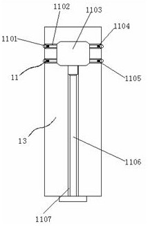
[0041] Embodiment 3: The lubricating structure 11 is composed of a sliding ball 1101, a flow channel 1102, a main chamber 1103, a cotton pad 1104, an active groove 1105, a push rod 1106 and a drainage groove 1107. The drainage groove 1107 is arranged at the bottom end of the rod body 13, The inside of the drainage groove 1107 is movably connected with a push rod 1106. The top of the drainage groove 1107 is provided with a main chamber 1103, and the two sides and two ends of the main chamber 1103 are respectively provided with multiple groups of flow channels 1102. One side of the flow channel 1102 There is also a movable groove 1105, and the inside of the movable groove 1105 is movably connected with a sliding ball 1101, and the inside of one side of the flow channel 1102 is fixedly connected with a cotton pad 1104;
[0042] The sliding bead 1101 is arranged inside the movable groove 1105, and the sliding bead 1101, the movable groove 1105 and the rod body 13 are arranged in co...
PUM
 Abstract
Description
Claims
Application Information
 - R&D
- Intellectual Property
- Life Sciences
- Materials
- Tech Scout
- Unparalleled Data Quality
- Higher Quality Content
- 60% Fewer Hallucinations
Browse by: Latest US Patents, China's latest patents, Technical Efficacy Thesaurus, Application Domain, Technology Topic, Popular Technical Reports.
© 2025 PatSnap. All rights reserved.Legal|Privacy policy|Modern Slavery Act Transparency Statement|Sitemap|About US| Contact US: help@patsnap.com


