
Machining mechanism and machining equipment

A processing mechanism and spindle technology, applied in the direction of metal processing equipment, metal processing machinery parts, measuring/indicating equipment, etc., can solve problems such as not being able to meet the processing depth, improve processing accuracy and processing efficiency, improve detection accuracy, and improve processing The effect of precision

Active Publication Date: 2021-04-30
SUZHOU VEGA TECH CO LTD
View PDF7 Cites 2 Cited by
  • Summary
  • Abstract
  • Description
  • Claims
  • Application Information

AI Technical Summary

Problems solved by technology

However, the processing equipment in the related art can no longer meet the requirements of higher processing depth and precision, so it is urgent to improve

Method used


Image

  • Machining mechanism and machining equipment
  • Machining mechanism and machining equipment
  • Machining mechanism and machining equipment

Examples


Embodiment Construction

[0037]Embodiments of the present invention are described in detail below, examples of which are shown in the drawings, wherein the same or similar reference numerals designate the same or similar elements or elements having the same or similar functions throughout. The embodiments described below by referring to the figures are exemplary only for explaining the present invention and should not be construed as limiting the present invention.

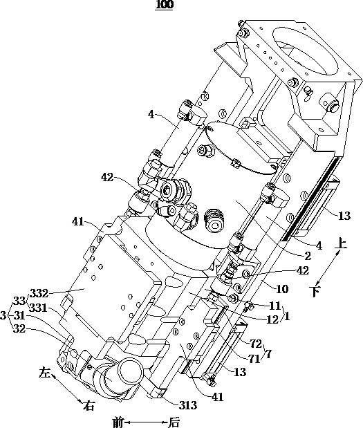
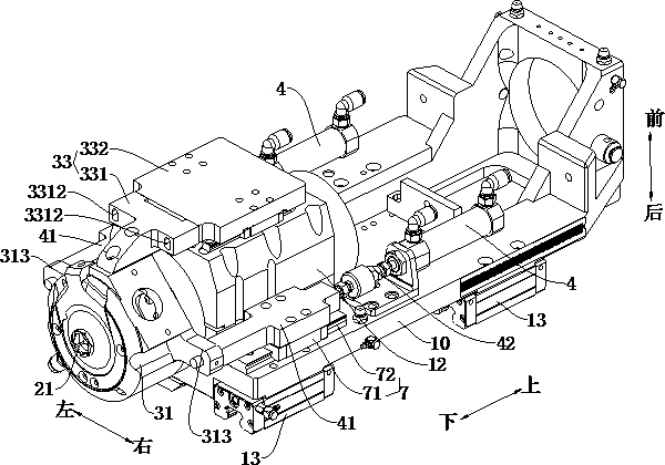
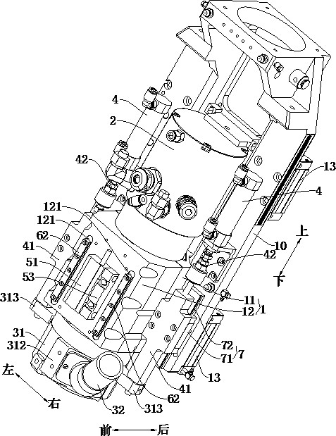
[0038] Refer below Figure 1-Figure 6 A processing mechanism 100 according to an embodiment of the present invention is described. The processing mechanism 100 can be used for processing PCB boards, such as drilling holes or edge milling for PCB boards.

[0039] Such as Figure 1-Figure 3 As shown, according to the processing mechanism 100 of the embodiment of the first aspect of the present invention, the processing mechanism 100 has a drilling function and / or a milling function, for example, the processing mechanism 100 can be a drill...


PUM


Abstract

The invention discloses a machining mechanism and machining equipment. The machining mechanism comprises a main shaft clamp used for mounting a main shaft, a main shaft mounting frame, a pressure foot assembly, a pressure foot driving mechanism, a position detection device and a first guide assembly. The main shaft clamp is arranged on the main shaft mounting frame, the pressure foot assembly is arranged on the main shaft mounting frame in a manner of being capable of moving up and down, the pressure foot assembly comprises a pressure foot and a connecting plate connected to the pressure foot, and the position detection device is used for detecting the current height position of the pressure foot in real time. The position detection device comprises a first detection component arranged on the main shaft clamp and a second detection component arranged on the connecting plate, the first guide assembly is used for guiding relative movement of the first detection component and the second detection component, and the first guide assembly comprises at least two sets of first sliding block guide rail pairs, wherein the two sets of first sliding block guide rail pairs are located on the two opposite sides of the position detection device. According to the machining mechanism, the machining depth can be controlled in real time, and the machining precision and the machining efficiency can be improved.

Description

technical field [0001] The invention relates to the field of processing equipment, in particular to a processing mechanism and processing equipment. Background technique [0002] For drilling equipment, CBD technology is used in related technologies to control the processing depth. Since CBD technology is used to obtain signals by conducting current through the board layer, when using CBD, the tool and presser foot may be turned on due to the winding of the tool. False positive problem arises. For edge milling equipment, in the related art, a length gauge is used for edge milling and depth control. However, when using a length gauge for edge milling and depth control, the length gauge must be used for depth detection before edge milling, which will affect processing efficiency. [0003] With the development of science and technology and the continuous high requirements of the market, the requirements for the processing depth and precision of the workpiece are getting higher...

Claims


Application Information

Patent Timeline
IPC IPC(8): B23Q17/22B23B19/02B23Q5/32
CPCB23Q1/70B23Q5/32B23Q17/22
Inventor 黄齐齐田来庞士君
Owner SUZHOU VEGA TECH CO LTD
Learn More