Ventilation pipe fixing frame for mining

A fixed frame and ventilation pipe technology, applied in mining equipment, mining equipment, earthwork drilling and mining, etc., can solve problems such as damage to mine balance, easy bolts to fall off, and mine gaps

Inactive Publication Date: 2021-04-30
梅碧章
0 Cites 0 Cited by

AI-Extracted Technical Summary

Problems solved by technology

[0003] Some existing ventilation pipe fixing frames are generally supported by hydraulic rods in the mine itself. The mine itself is not stable, and the ventilation pipes are mostly made of metal, which is heavy. When installing, use screws to penetrate the top of the mine , use brackets to fix the ventilation pipes, and the bolts driven in will easily cause gaps in the mine, which will destroy the balance...

Method used

The present invention provides a kind of ventilating pipe fixing frame for mining, by described supporting structure 3, described fixed plate 1 is supported and fixed on the top of mine cave, and the top of general mine cave is arched, is convenient to make described fixed plate 1 is more suitable for the top of the mine, which is convenient for the support structure 3 to support the fixed plate 1, avoids fixing the fixed plate 1 on the top of the mine by screws, and increases the support for the mine , the connection structure 6 is threadedly connected with the fixed structure 2, the frame pipe structure 4 is fixed on the bottom end of the connection structure 6, and the frame can be easily adjusted by turning the top end of the connection structure 6 The distance between the pipe structure 4 and the fixed structure 2, when the top end of the connecting structure 6 is rotated, the bottom end may not be rotated, because the bottom end of the fixed structure 2 is rotating, so that through the connecting structure 6. The frame tube structure 4 installed can change the direction and position without being inserted into the ventilation duct 7, so as to facilitate the installation of the ventilation duct 7. After the ventilation duct 7 is inserted into the inside of the frame tube structure 4,...

Abstract

The invention provides a ventilation pipe fixing frame for mining. The ventilation pipe fixing frame for mining comprises a fixing plate, a supporting structure, a fixing structure, a connecting structure, a pipe erecting structure, a clamping structure and a ventilation pipeline, wherein the top face of the supporting structure abuts against the two ends of the bottom face of the fixing plate, the supporting structure comprises a hydraulic supporting column, an ejector head, a supporting plate and an anti-skid pad, the top face of the anti-skid pad abuts against the two ends of the bottom face of the fixing plate, the supporting plate is fixed at the bottom end of the anti-slip pad, the ejector head is fixed at the middle position of the ground of the supporting plate, the fixing structure is fixed at the middle position of the bottom face of the fixing plate, the connecting structure is mounted at the bottom end of a movable rod; the pipe erecting structure is fixed to the bottom end of a fixing block, and the clamping structure penetrates through the two ends of the side wall of the top face of a pipe erecting sleeve. The ventilation pipe fixing frame for mining has the advantages that a plurality of ventilation pipes are convenient to mount, and the balance of a mine is not damaged.

Application Domain

Mining devices

Technology Topic

Ventilation ductVentilation tube +7

Image

  • Ventilation pipe fixing frame for mining
  • Ventilation pipe fixing frame for mining
  • Ventilation pipe fixing frame for mining

Examples

  • Experimental program(1)

Example Embodiment

[0020] The present invention will be further described below in conjunction with the accompanying drawings and embodiments.
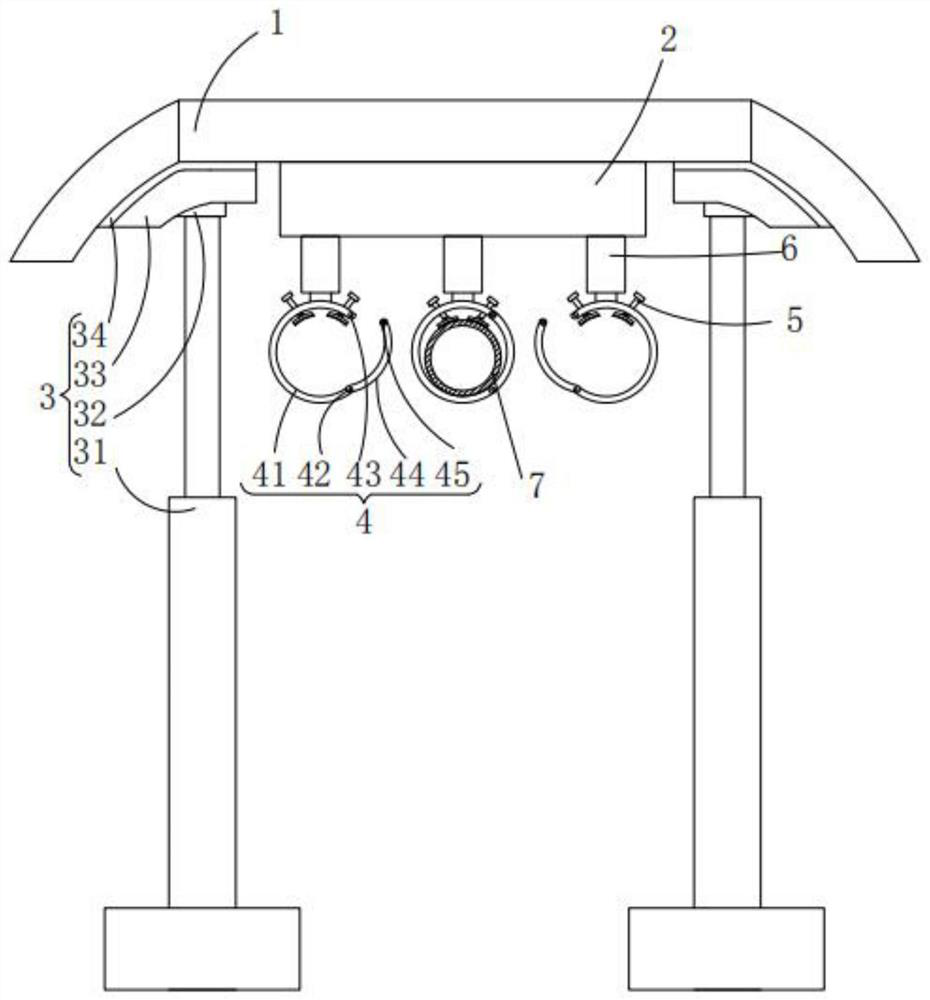
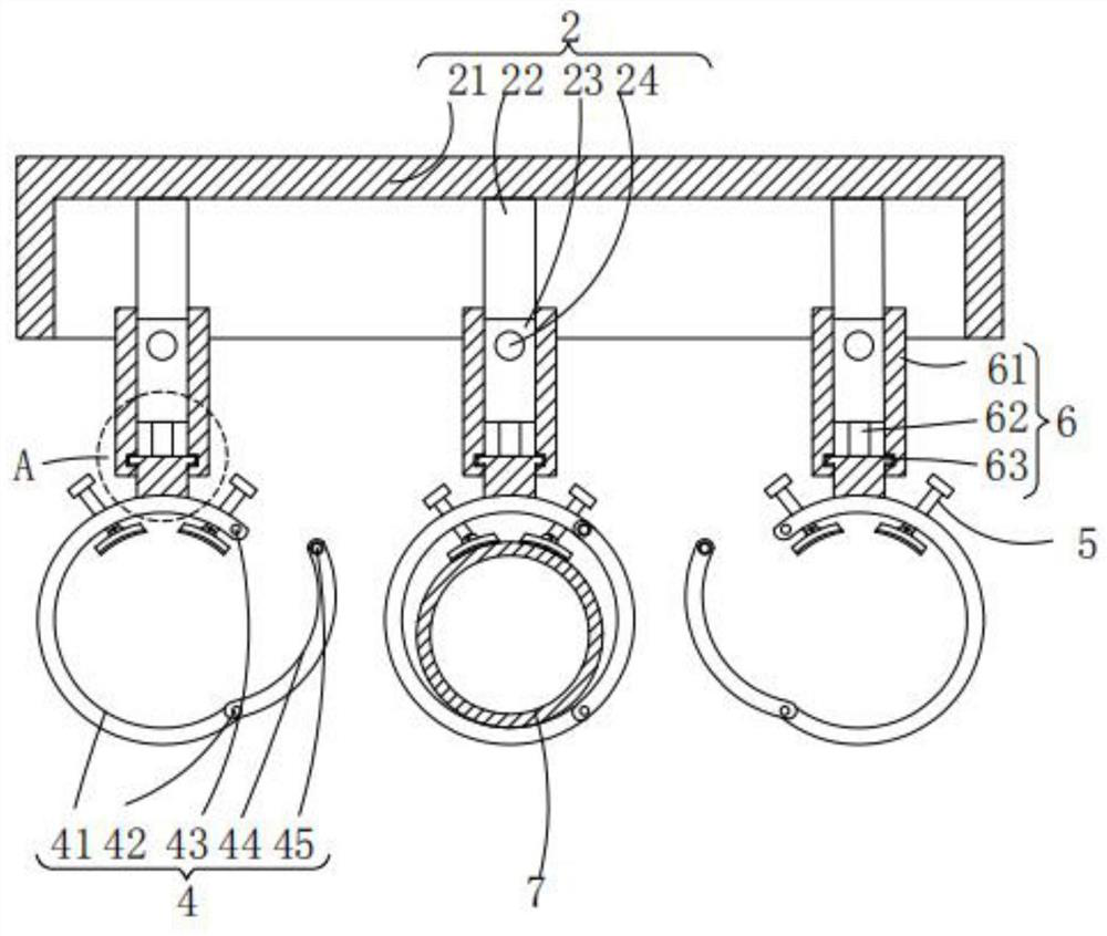
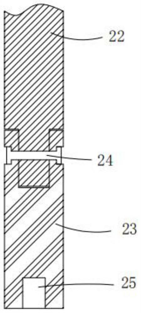
[0021] Please refer to figure 1 , figure 2 , image 3 , Figure 4 and Figure 5 ,in, figure 2 for figure 1 Structural schematic diagram of the fixed structure shown; image 3 for figure 1 The schematic diagram of the connection structure of the movable rod shown; Figure 4 for figure 1 Schematic diagram of the clamping structure shown; Figure 5 for figure 1 Shown in A is an enlarged schematic diagram of the structure. The ventilation pipe fixing frame for mining includes: a fixing plate 1; a supporting structure 3, a fixing structure 2, a connecting structure 6, a frame pipe structure 4, a clamping structure 5, and a ventilation pipe 7, and the top surface of the supporting structure 3 resists the fixing The two ends of the bottom surface of the plate 1, the support structure 3 includes a hydraulic support column 31, a plug 32, a support plate 33 and an anti-slip pad 34, the top surface of the anti-slip pad 34 is in contact with the two ends of the bottom surface of the fixed plate 1, and the The support plate 33 is fixed on the bottom of the anti-skid pad 34, the top 32 is fixed on the center of the support plate 33 ground, and the hydraulic support column 31 is fixed on the bottom of the top 32; the fixed structure 2 is fixed at the center of the bottom surface of the fixed plate 1, the fixed structure 2 includes a fixed frame 21, a fixed column 22, a movable rod 23, a first socket 24 and a slot 25, and the fixed frame 21 is fixed on the In the center of the bottom surface of the fixed plate 1, the fixed column 22 is fixed on the top surface inside the fixed frame 21, the movable rod 23 is installed on the bottom end of the fixed column 22, and the first socket 24 runs through the The side wall at the top of the movable rod 23 and the side wall at the bottom of the fixed column 22, the draw-in groove 25 is located inside the bottom end of the movable rod 23; the connecting structure 6 is installed at the bottom of the movable rod 23 end, the connection structure 6 includes a threaded sleeve 61, a clamp 62 and a fixed block 63, the threaded sleeve 61 is installed on the bottom end of the movable rod 23, and the fixed block 63 is installed on the bottom of the threaded sleeve 61 end, the clamping column 62 is fixed on the top of the fixed block 63; the frame tube structure 4 is fixed on the bottom end of the fixed block 63, and the frame tube structure 4 includes a frame tube sleeve 41, a second socket 42, screw holes 43, arc-shaped plates 44 and bolts 45, the frame pipe sleeve 41 is fixed on the bottom end of the fixed block 63, the screw hole 43 is located on the side wall of one end of the frame pipe sleeve 41, the The arc-shaped plate 44 is installed on the other end of the frame pipe sleeve 41, the second socket 42 passes through the side wall of the arc-shaped plate 44 and is connected to the side wall of the frame pipe sleeve 41, and the bolt 45 Through the other end of the arc-shaped plate 44; the clamping structure 5 penetrates both ends of the top side wall of the frame sleeve 41, and the clamping structure 5 includes a rotary head 51, a stud 52, and a connecting block 53 , a rotating shaft 54, a clamping piece 55 and a pad 56, the stud 52 runs through the two ends of the top side wall of the frame sleeve 41, the rotating head 51 is fixed on one end of the stud 52, the The connecting block 53 is installed on the other end of the stud 52, the rotating shaft 54 ​​runs through the side wall of the top end of the connecting block 53 and the side wall of the bottom end of the stud 52 respectively, and the clamping piece 55 is installed on the The bottom end of the connection block 53 and the pad 56 are fixed on the bottom surface of the clamping piece 55 ;
[0022] In the specific implementation process, such asfigure 1 As shown, the sidewalls at both ends of the fixing plate 1 are arc-shaped, and the sidewall at one end of the support plate 33 is also arc-shaped, and the hydraulic support column 31 is supported and fixed by the support plate 33. The plate 1 is generally arched at the top of the mine, so that the fixed plate 1 is more suitable for the top of the mine, so that the hydraulic support column 31 can support the fixed plate 1 through the support plate 33 .
[0023] In the specific implementation process, such as figure 2 and image 3 As shown, the fixed column 22 and the movable rod 23 are rotationally connected through the first socket 24, and the diameters of the fixed column 22 and the movable rod 23 are equal, and the fixed column 22 and the movable rod 23 are rotatably connected. The thread directions of the side walls of the movable rod 23 are the same, and since the opening at one end of the frame pipe sleeve 41 is not much larger than the diameter of the ventilation duct 7, the movable rod 23 can be rotated to make the frame pipe sleeve 41 The opening direction of the frame is changed, so that the frame pipe cover 41 is inserted into the ventilation duct 7 for fixing.
[0024] In the specific implementation process, such as figure 2 and Figure 5 As shown, the clamping column 62 slides inside the clamping groove 25, and the threaded sleeve 61 is threadedly connected with the fixed column 22 and the movable rod 23 respectively, and the bottom end of the threaded sleeve 61 is connected with the The fixed block 63 is rotatably connected, and by rotating the threaded sleeve 61, the distance between the frame pipe cover 41 and the fixed frame 21 can be changed. During installation, although it is beneficial to the fixing of the ventilation duct 7, it does not This facilitates the installation of the ventilation duct 7 .
[0025] In the specific implementation process, such as figure 1 and figure 2 As shown, one end of the arc-shaped plate 44 is rotatably connected to one end of the frame sleeve 41 through the second shank 42, and the other end of the arc-shaped plate 44 is connected to the frame through the bolt 45. The other end of the pipe cover 41 is fixedly connected, and the opening at one end of the frame pipe cover 41 is larger than the maximum diameter of the ventilation duct 7, which facilitates the closing and unfolding of the opening at one end of the frame pipe cover, so that the ventilation duct 7 is inserted into the After the inside of the frame pipe sleeve 41 , the arc-shaped plate 44 closes the opening of the frame pipe sleeve 41 so that the ventilation duct 7 will not be separated from the inside of the frame pipe sleeve 41 .
[0026] In the specific implementation process, such as figure 1 As shown, the stud 52 is rotatably connected to the connecting block 53 through the rotating shaft 54, and the connecting block 53 is rotatably connected to the clamping piece 55, and the ventilation duct 7 is inserted into the After the inside of the rack pipe sleeve is described, by rotating the stud 52, the stud 52 pushes the clamping piece 55 to stick to the side wall of the ventilation duct 7, and the stud 52 does not apply pressure. The direction of the clamping piece 55 will be changed, so that the clamping piece 55 is firmly against the side wall of the ventilation duct 7 , so that the ventilation duct 7 is fixed inside the frame sleeve 41 .
[0027] The operating principle of the ventilation pipe fixing frame for mining provided by the invention is as follows:
[0028] When installing, the top surface of the fixed plate 1 is first attached to the top of the mine, and then the hydraulic support column 31 is used to push up the support plate 33 fixed by the plug 32, so that the support plate 33 The top surface is in contact with the two ends of the bottom surface of the fixed plate 1. Since the two ends of the fixed plate 1 are arc-shaped, and one end of the support plate 33 is also arc-shaped, the support plate 33 is in contact with the fixed plate. The plate 1 is more appropriate, so that the support plate 33 supports and fixes the fixed plate 1 on the top of the mine through the hydraulic support column 31, and the fixed frame 21 is fixed at the center of the bottom surface of the fixed plate 1, The inside of the fixed frame 21 is fixed with the fixed column 22, the bottom end of the fixed column 22 is connected with the movable rod 23 through the first shank 24, and the movable rod 23 is connected with the fixed column. The diameters of 22 are equal, and the side walls have threads in the same direction. When installing the ventilation sleeve 7, first connect the threaded sleeve 61 that is rotationally connected with the fixed block 63 to the bottom of the movable rod 23. end, so that the post 62 fixed on the top of the fixed block 63 is inserted into the inside of the slot 25 provided at the bottom end of the movable rod 23, so that the fixed block 63 can be rotated when the threaded sleeve 61 is turned Will not follow the rotation, the bottom end of the fixed block 63 is fixed with the frame pipe sleeve 41, and one end of the frame pipe sleeve 41 is rotationally connected with the arc-shaped plate 44 through the second shank 42, And the opening at one end of the frame pipe sleeve 41 is greater than the diameter of the ventilation duct 7, then the ventilation duct 7 is moved to the height of the frame pipe sleeve 41, and then the frame pipe sleeve 41 is driven to pass through the The movable rod 23 rotates with the fixed column 22 to change the position of the frame pipe sleeve 41, and the ventilation duct 7 is inserted into the inside of the frame pipe sleeve 41. Since the inner bottom surface of the frame pipe sleeve 41 is arc-shaped, The ventilation duct 7 can be restricted inside the frame pipe sleeve 41, and then by rotating the arc plate 44, the other end of the arc plate 44 is fixed on the frame pipe sleeve by the bolt 45 41 to close the frame sleeve 41, and then by turning the rotary head 51, the stud 52 pushes the clamping piece 55 to be close to the side wall of the ventilation duct 7, in the When the stud 52 rotates, the clamping piece 55 will not rotate. When the clamping piece 55 exerts pressure on the side wall of the ventilation duct 7, the stud 52 rotates through the connecting block 53, thereby changing The clamping piece 55 is applied to the direction of the side wall force of the ventilation duct 7, so that the inner sidewall of the clamping piece 55 can be attached to the side wall of the ventilation duct 7, so that the force exerted by the stud 52 Pressure can act on the ventilation duct 7, the ventilation duct 7 is fixed in the inside of the frame pipe cover 41, and then the threaded sleeve 61 is rotated so that the top of the threaded sleeve 61 is in contact with the fixed The column 22 is connected, so that the threaded sleeve 61 pulls the frame tube cover 41 to rise, reducing the distance between the fixed frame 21 and the frame tube cover 41, so that the Said threaded sleeve 61 restricts the rotation of said fixed post 22 and said movable rod 23, so that said ventilation duct 7 is fixed, which has the advantage of being convenient to install a plurality of ventilation ducts without destroying the balance of the mine itself.
[0029] Compared with related technologies, the ventilation pipe fixing frame for mining provided by the invention has the following beneficial effects:
[0030] The invention provides a ventilation pipe fixing frame for mining. The fixing plate 1 is supported and fixed on the top of the mine through the support structure 3. Generally, the top of the mine is arched, so that the fixing plate 1 is more suitable. The top of the mine is convenient for the support structure 3 to the support of the fixed plate 1, avoiding the fixing of the fixed plate 1 on the top of the mine by screws, and increasing the support of the mine. The connection structure 6 is threadedly connected with the fixed structure 2, and the frame pipe structure 4 is fixed on the bottom end of the connection structure 6. By turning the top end of the connection structure 6, it is convenient to adjust the frame pipe structure 4 The distance between the fixed structure 2 and the bottom end of the connecting structure 6 can not be rotated when the top end is rotated. Since the bottom end of the fixed structure 2 is rotated, the connection structure 6 installed The frame tube structure 4 can change the direction and position when it is not inserted into the ventilation duct 7, so as to facilitate the installation of the ventilation duct 7. One end of the clamping structure 5 on the side walls at both ends of the top surface of the frame tube structure 4 makes the other end of the clamping structure 5 touch the side wall of the ventilation duct 7 to fix the ventilation duct 7 Inside the frame tube structure 4, when one end of the clamping structure 5 is rotated, the other end of the clamping structure 5 will not follow the rotation, but the other end of the clamping structure 5 can be rotated according to the The force received by the side wall of the ventilation duct 7 changes the stressed area of ​​the other end of the clamping structure 5, so that the force of the clamping structure 5 acts on the side wall of the ventilation duct 7, and then rotates the The top of the connecting structure 6, so that the connecting structure 6 draws closer to the distance between the frame pipe structure 4 and the fixed structure 2, so that the top of the connecting structure 6 limits the movable part of the fixed structure 2, The frame tube structure 4 is fixed on the bottom surface of the fixed structure 2 through the connecting structure 6, and the ventilation duct 7 is fixed, so that it is convenient to install multiple ventilation ducts without destroying the balance of the mine itself. advantage.
[0031] The above is only an embodiment of the present invention, and does not limit the patent scope of the present invention. Any equivalent structure or equivalent process conversion made by using the description of the present invention and the contents of the accompanying drawings, or directly or indirectly used in other related technologies fields, all of which are equally included in the scope of patent protection of the present invention.

PUM

no PUM

Description & Claims & Application Information

We can also present the details of the Description, Claims and Application information to help users get a comprehensive understanding of the technical details of the patent, such as background art, summary of invention, brief description of drawings, description of embodiments, and other original content. On the other hand, users can also determine the specific scope of protection of the technology through the list of claims; as well as understand the changes in the life cycle of the technology with the presentation of the patent timeline. Login to view more.
Why Eureka
Try Eureka