Eureka AIR delivers breakthrough ideas for toughest innovation challenges, trusted by R&D personnel around the world.

Outdoor rapidly-installed antenna rack for electronic information engineering

A technology of electronic information and antenna racks, which is applied in the direction of antenna supports/installation devices, etc., can solve the problems of inconvenient assembly and disassembly of antenna racks, unstable installation, and inability to flexibly adjust the installation angle, etc., to achieve a complete and compact structural design, easy to disassemble Easy to assemble and increase the installation range

Inactive Publication Date: 2019-06-14
合肥锟特奇科技有限公司
View PDF8 Cites 5 Cited by
  • Summary
  • Abstract
  • Description
  • Claims
  • Application Information

AI Technical Summary

Problems solved by technology

[0004] The technical problem to be solved by the present invention is to overcome the disadvantages of inconvenient assembly and disassembly of the existing antenna rack, the inability to flexibly adjust the installation angle, and the insufficient stability of the installation, and provide an antenna rack for electronic information engineering to be quickly installed outdoors, thereby solving the above problems

Method used


Image

  • Outdoor rapidly-installed antenna rack for electronic information engineering
  • Outdoor rapidly-installed antenna rack for electronic information engineering

Examples


Embodiment Construction

[0017] The technical solutions in the embodiments of the present invention will be clearly and completely described below in conjunction with the accompanying drawings in the embodiments of the present invention. Obviously, the described embodiments are only some of the embodiments of the present invention, not all of them. Based on The embodiments of the present invention and all other embodiments obtained by persons of ordinary skill in the art without making creative efforts belong to the protection scope of the present invention.

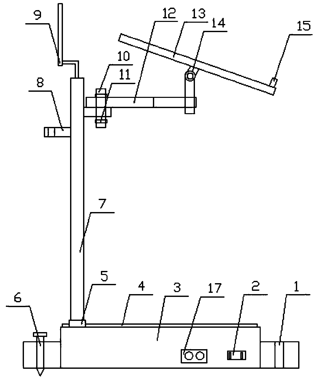
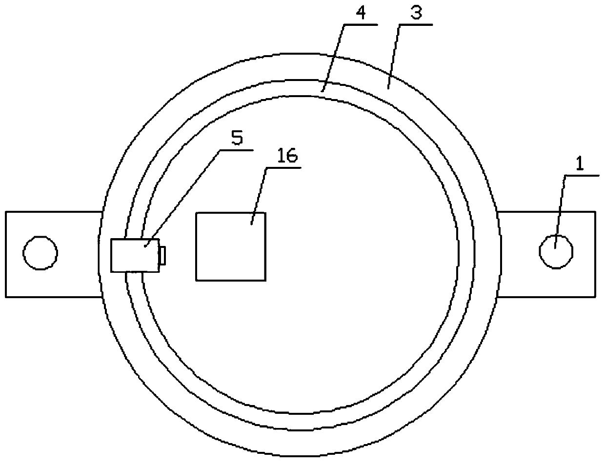
[0018] see Figure 1-2 , the present invention provides a technical solution: an antenna mount for electronic information engineering users to quickly install outdoors, including a base 3, a support rod 7, a connecting rod 12 and an antenna mounting plate 13, and two ends of the base 3 are provided with mounting holes 1 , one side of the base 3 is provided with a charging interface 2, one side of the charging interface 2 is provided with a contr...


PUM


Abstract

The invention discloses an outdoor rapidly-installed antenna rack for electronic information engineering. The outdoor rapidly-installed antenna rack comprises a base, a support rod, a connection rod and an antenna installation plate, wherein installation holes are formed in two ends of the base, a charging interface is arranged in one side of the base, a guide rail is arranged at the top of the base and is connected with a sliding block in a sliding way, the guide rail is electrically connected with a miniature motor in the base, the support rod is fixedly connected with the top of the slidingblock, fixed rods are arranged at two sides of the top of the support rod, one end of the connection rod and the fixed rods are connected by dual-head bolts, a rotation support is fixedly connected with the bottom of the antenna installation plate, a bottom end of the rotation support is in threaded connection with the other end of the connection rod, the connection rod and the support rod are oftelescopic structures, the height is convenient and free to adjust, the free rotation adjustment angle of the support rod can be automatic by the sliding block of the support rod at the guide rail, and the operation labor intensity of a worker is reduced; the fixed rods are arranged in two directions of the support rod, and the installation range is expanded; and by the outdoor rapidly-installedantenna rack, multi-angle installation and adjustment of the antenna can be achieved.

Description

technical field [0001] The invention relates to the technical field of antenna stand equipment, in particular to an outdoor quick-installation antenna stand for electronic information engineering. Background technique [0002] The base station, that is, the public mobile communication base station, is a form of radio station, which refers to a radio transceiver station that transmits information between mobile phone terminals through a mobile communication switching center in a certain radio coverage area. The construction of mobile communication base stations is an important part of the investment of mobile communication operators in my country. The construction of mobile communication base stations is generally carried out around factors such as coverage, call quality, investment benefits, difficulty of construction, and convenient maintenance. With the development of mobile communication network services in the direction of dataization and packetization, the development t...

Claims


Application Information

Patent Timeline
Patent Type & Authority Applications(China)
IPC IPC(8): H01Q1/12
Inventor 胡洁
Owner 合肥锟特奇科技有限公司
Why Eureka
Eureka Blog
Learn More